Monday, April 30, 2012

Pneumatic Antenna Launchers for sale

UPDATE 4.15.2014: Due to various reasons (personal schedule, parts availability, business feasibility, etc) , I have decided to discontinue the Antenna Launcher product line. If things change, I'll post here but as of now there are no near future plans to make any antenna launchers. Sorry for any caused inconvenience!

UPDATE Sep 2013: Pictures of the new style BDAS-2 Launcher.

Complete BDAS-2 kit - this is what you'll receive if you order one.
The User-Manual is available for download (check the link in this post)

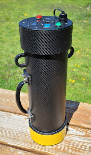
The look now is more consistent with a trade name like "iLauncher 2S"

Surface materials are more durable than paint and the carbon fiber finish looks great!

UPDATE Mar 21 2013:  The BDAS-2 Antenna Launcher is currently out of stock. Production will resume in late April with units in stock during the first week of May. Please don't wait until the last moment - in the month before Field Day, I get overwhelmed with orders and you might not be able to get it in time.
Now up to Revision 2, with a new "Carbon Fiber Look". Pictures will follow, but this newly designed look is totally "Space Age" and has more clean and modern appearance. New materials were used and the finish is also more durable and less prone to wear and scratches than the old painted surface. The painted version will still be available upon special request at a slightly higher price. The Ramrod in Revision 2 is also updated - now the handle is made out of two parts with friction assembly for an improved portability and shorter storage length (not pictured above).
Lead times for new orders on "Out-of-Stock" products is 2 to 3 weeks. "In stock" items ship within 3 business days after the payment clears.
BDAS-2 Antenna Launcher  (current version) - $299
BDAS-1 Antenna Launcher (legacy) - Special Orders only (TBA)
Complete Kit Includes: Antenna Launcher, Zip Reel with 150 yards Leader Line, a set of 3 weighted projectiles (1x 6oz, 2x 4oz) and a Ramrod
BDAS-2 Antenna Launcher / "T-shirt Cannon" option - $249
"T-shirt Cannon" option - no Zip Reel, no Leader Line and no Projectile Set are included. A 2.5" coupler is included along with BDAS-2 Launcher and a Ramrod.
All orders ship via USPS Standard parcel service or UPS Ground- customer pays actual shipping fee for 26x13x8" box / 14 Lbs from Zip code 06804. Continental US only.
Local Pickup is also available at no additional charge.


My article on the Pneumatic Antenna Launcher generated huge amount of interest. A bunch of web sites like Hack-a-Day, Make Magazine, Wonder How To and others featured the article and increased the popularity even more. Since then, people are asking from assistance with building their own launchers to wanting to buy a finished product. I end up making a small production run to satisfy these needs. Field Day is coming and I am left with a few  launchers for sale from this run. I have not decided yet if I'll keep making them - the process is rather time consuming. If I decide to go on, I will likely create a separate web site.
These launchers are no-compromise, top-shelf product for people who demand high quality (and they look great too!). Ready to use - no assembly is required! Each kit includes a Launcher, a Zip Reel loaded with 150 yards of 50lb Test Hi-Vis Yellow Spectra Line, a Set of 3 projectiles (Weighted Tennis Balls - 2x 4 oz and one 6 oz) and a Ramrod. For more information, specs and details, please download the User Manual before ordering (for those who already purchased a launcher before 2013 - this is a revised  version of the manual - please download it and use it instead of the printed one included with the Launcher). Shipping to Continental US only! Price is set to $299 + actual shipping charge. For ordering, please email: ae1s AT arrl.net. Payments via PayPal or Cashier Check or cash for Local Pickup. Ships in 3 business days.

 "Graphite - Yellow", "Graphite - Orange" and "Steampunk"

"Steampunk" is the most popular finish people were asking for. Somebody even ordered one these to use as a "T-Shirt Cannon" for his band.

 Picture of the Trigger Valve Assembly

 Zip Reel with Leader Line.. A nifty Line Cutter is mounted on the bottom.

 The unique "Safety" feature in "ON" position 

 "Graphite - Orange" - The combination of metallic / graphite look and bright signal orange looks really nice.

 Another angle on the Trigger Valve and mounting bracket with the "Safety" Strap
Safety was a priority when building these launcher. Only pressure rated fittings were used - no drilling and epoxy gluing of PVC parts here. 

All launchers feature a Safety Relief Valve. Every single junction is Solvent Welded. The attention to detail is obvious everywhere you look. During painting, every part was carefully masked - note how the front face of pressure tank cap is painted and the clean edge between colors.

"Graphite Yellow"

Thursday, March 29, 2012

Yet another set of VNA calibration standards

This time - Type-N female. One of the most critical components in DIY calibration standard is the connector used to build it. The market is flooded with all kinds of connectors but most of them are of really shoddy quality (sorry to bash on China but that's where all the junk comes from). After playing with and testing different connectors, my conclusion is that one is shooting in the dark ordering connectors from China to use for DIY cal standards. Very rare there will be good enough connector from China, even for 60 MHz VNA cal standard. It is unbelievable the amount of sub-standard junk they make!
The best way to go about is to find high-quality brand name connectors on the surplus market. Ebay is also a good source but it takes time and patience to find what you need.
I've mentioned before that having a few sets of cal standard -different connector type and gender is very useful! I needed a good set of female Type-N OPEN and SHORT (I have a commercial LOAD).
One can buy on eBay a used female Type-N to female-SMA adapter of REALLY high quality for about $10/pc - I am talking about Amphenol 131-445 / HP-Agilent #1250-1404. Even at $30 this adapter is still a bargain. It is actually a bulkhead female Type-N used for commercial VNAs, Spectrum analyzer and other lab equipment. The body is machined from stainless steel, the pin receptacle is gold-plated copper-beryllium and it is using very interesting dielectric.
The center dielectric is made of a small plastic disc with 6 dead holes - 3 on each side of the disc. In each set the holes are at 120 degrees and the two sets are offset by 60 degrees from each other. As a result - the center pin receptacle is supported only by 6 very little plastic spokes. The holes are fairly large leaving mostly air around the center. This is as close as it gets to DIY air dielectric while still have strong mechanical support for the pin receptacle. I think the reason for the "dead holes" is to stop dust and contaminants getting inside.

For the OPEN I just cut the center pin flush to the dielectric. The dielectric disc has a brass sleeve in the center. A dab of solder fixes the pin receptacle to the sleeve. The disc is not made from teflon and soldering time and temperature should be minimal. One can easily measure the distance to the reference plane and calculate the offset. The stray capacitance and losses are minimal due to the dielectric's construction.
The SHORT is made by soldering a "washer" of tin-plated brass to the center pin. When the back shell (the gold plated part) of the connector is screwed in place it presses onto the outer part of the washer and makes the electrical connection to the connector's body. I left the rest of the center pin intact - it goes inside the teflon dielectric of the back SMA part for additional mechanical support.

Thursday, March 1, 2012

Crystal Test Fixture

Jack Smith, K8ZOA posted an interesting paper on "Measurement approaches of Crystal Motional Parameters" and designed a test fixture (based on the "classic" IEC 444 pub. fixture) to aid such measurements. The fixture is rather simple - it is comprised of two impedance matching attenuator pads, presenting the crystal resonator with a low, accurate impedance (12.5 Ohms, the center of the 5-20 ohm range of crystal's series resistance) during transmission measurements and transforming it from and to the 50 ohms impedance of the source and detector. These attenuators act as sort of a "buffer" - because of the transformation, the crystal "sees" only the accurate 12.5 Ohm input and output impedance regardless of the source's and detector's return loss.
Each attenuator is in Pi-pad configuration with attenuation of approx. ~15 dB (due to standard resistor values, the actual calculated attenuation for each pad is 14.81 dB). Input shunt is 158.0 Ohms, series resistor is 66.50 Ohms and Output shunt is 14.30 Ohm (ideal calculated value is 14.20) - all in 1206 packages 1% tolerance.
It occurred to me that Ivan Makarov's N2PK VNA Reflection Bridge PCB can be modified very easily to accommodate both pads and I can use the board to build the entire test fixture. The modification is very simple!

I used a Dremel Tool to drill (Carbide PCB drill bit #71, 0.0260") 3 holes (0.1" spacing) for the crystal socket / header and a small end mill bit to make to cut two trace cuts.

The socket is a gold-plated machined type - it can be cut from an IC machined socket. The HC-49 crystal package fits perfectly in the socket. An adapter can be made if the fixture is to be used with other components with larger diameter leads.
The socket is installed on the reverse (solid ground plane) side of the board. The middle pin is soldered to the ground plane on the component side. Copper is removed around the two side holes (on the socket side) so it will clear the bottom part of the socket pins. The ground plane should clear each socket pin by at least 1 mm around (the diameter of the no-copper area around each hole is about 0.1"). Again, a round end-mill bit or a big round engraving diamond file bit on the Dremel Tool will do the job.

This picture shows the configuration of the resistors in each Pi-pad. The ideal value for the output shunt is 14.2 ohms, so I installed 2.2k (1%) resistors in parallel with each 14.3 resistor to bring the resistance down. I used my LCR meter to select all attenuator resistors in order to have values as close as possible to the ideal calculated values. RF screen (cut from tin-plated brass sheet) is installed across the board, on the component side to shield the output from the input. The unnecessary PCB pads are flooded with solder and connected to the common ground plane.

Two edge mount SMA (f) are installed 2" apart. The 2" spacing matches my N2PK VNA port spacing so I can install the fixture directly on the VNA ports without the use of any cables.

Two copper-beryllium contact clips - one on each side of the socket are soldered to the ground plane. These spring clips connect the resonator's can to ground when the crystal is inserted and provide additional mechanical support for the crystal package.
The picture also shows the THRU calibration jumper and 50 ohm load test jumper.

Tuesday, February 21, 2012

Reflection Bridge with Type-N connectors

I always try to avoid using "between-series" adapters - there are so many out there with questionable quality. Sometimes these adapters are just the "necessary evil". In an attempt to reduce the need for adapters, I built 3 different reflection bridges for my N2PK VNA - BNC, SMA and Type-N.
From a mechanical point of view, mating a bridge directly onto 2 fixed distance ports presents a challenge - the connectors must be aligned perfectly. These are precision connectors and even the smallest misalignment will cause stress to the pin/receptacle, uneven wear and possibly damage. Using Type-N flange connectors on the reflection bridge will form too rigid junction and they are difficult to install with such great precision. On the other hand I prefer somewhat rigid connection and don't want to use flexible coax as it introduces phase instability when bent or twisted. A few tenths of the millimeter lateral "play" in the connectors will be enough to take care of small misalignment.
To build the Type-N bridge I used a pair of male Type-N connectors (solder type, Digikey p/n ACX1132-ND) on ~3 cm pieces of semi-rigid coax (RG-402 - solid copper tube shield, not the hand-conformable type). The coax is inserted in a brass tube (very slightly larger than the diameter of the coax, 2.1 cm length, K&S Engineering 3/16 x .014 Stock #129) that goes thru the wall of the aluminum enclosure and it is soldered inside to a brass plate. A second, larger diameter brass tube (2 cm length, K&S Engineering 7/32 Stcok #130) goes over the small diameter tube but does not go thru the wall. The small diameter tube provides stress-relief on pull action, as one end of the RG-402 is soldered to it. The larger diameter brass tube goes over the solder collar in the base of the male Type-N connector and it is compressed between the enclosure and connector, providing stress-relief on push action.
The whole assembly might be a little over-engineered but it is very sturdy and gives me the few tenths of millimeter lateral flexibility at the connector end without being too flexible. It, also protects the RG-402 from accidental permanent bending and damage.

The small diameter brass tube goes thru the wall and together with the protruding copper shield of the RG-402 coax is soldered to a brass plate and the PCB's ground plane. It is critical that the holes in the aluminum enclosure are just big enough for the small diameter brass tube to be inserted with no "play"as the flexibility needs to come from the exposed length of the brass tube. An SMA connector is installed for the DDS source termination (needed for improved low frequency measurements).

Heat-shrink tubing color-coded the IN and OUT of the reflection bridge. For the DUT port I installed a high-quality Amphenol 131-445 / HP-Agilent #1250-1404 female Type N connector. This instrument grade connector has a SMA(f) on the back. A corresponding SMA(m) with really short pigtail (~4-5 mm) was used for connection to the bridge. I had to make a cut-out in the PCB to accommodate the SMAs.

Because of the custom Type-N connectors, I was able to fit the bridge in a lower profile enclosure - same type I used for my RF-IV sensors - Bud Industries CN-5701 (Digikey p/n 377-1512-ND)

Tuesday, January 17, 2012

My 2nd Generation N2PK VNA

I am just about done with my second generation N2PK VNA. The first one I've built is mainly for portable / field use, while this larger unit is for my work bench.
Main differences over my first generation unit:
- built-in USB interface using HSUSB (both VNAs are based on the parallel port PCB ver. 4.3)
- larger enclosure with separate shielded RF deck compartment and PS/USB rear compartment (Hammond 1455T2201, Digi-Key p/n HM905-ND)
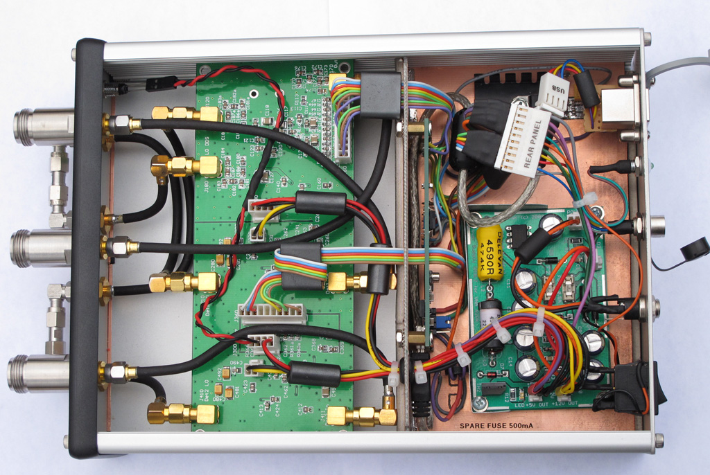
- Instrument grade, stainless steel precision Type-N and SMA front panel connectors (Amphenol 131-445 / HP-Agilent #1250-1404)
- All internal RF connections are made with Conformable semi-rigid RG-402 coax (Belden 1673A)

The larger enclosure provides better cooling and thermal stability. I have separated the space into two compartments in order to improve the RF shielding and noise floor. Furthermore, the use of semi-rigid coax requires more space. I must say that working with semi-rigid coax is not an easy thing, even when using hand-conformable type. The connections must be fabricated with a great precision, avoiding re-bending of the coax. I used scrap pieces coax to get the right shape of each link and then carefully followed the shape with the actual coax, bending it only once.

The front panel is using very-high quality lab-grade (read: very expensive) RF connectors. I also improved on the front panel layout. A front panel LED indicates +5V power to the DDS chips.

The rear panel with industrial grade Type-B USB connector. The LED next to the connector indicates power to the USB interface. The USB interface board can be powered by the host computer or by the internal power supply (jumper selectable). I also made a small modification to the HSUSB board to incorporate the VNA PWR DETECT signal directly on the board itself. An Accessory connector is installed for connecting the S-parameter test set, RF-IV test head or any of the two transverters. It is a 6 pin connector with all necessary control signals and +9V power for the accessories.

The power supply mounting bed. The N2PK VNA power supply provides +5v (using a switching regulator), +9V and +12V (linear regulators). There are "crowbar" type over-voltage protections for both, the +5 and +12 V as well as extensive filtering and power conditioning. This picture is with the top RF shield of the PS board removed. The HSUSB board is mounted vertically using stand-offs, on the back wall of the RF compartment shield. The linear regulator and heatsink next to the PS board is for +9V line going to the ACC connector.


The PS mount was constructed by soldering two pieces of copper-clad FR4 PCB material.
On the bottom I mounted copper-beryllium contact clips for better grounding to the aluminum enclosure. When installed, it is a tight fit in the aluminum enclosure, effectively shielding the VNA board from the switching PS and USB interface board. Using such mount, I was able to install everything in the enclosure without drilling any holes and using external screws - it is pure aesthetics but the VNA does look sharp that way.

The noise floor of Detector 1 is slightly better than -120 dB for the most part (0.05 to 30 MHz it is about -122 dB).

In addition, I made a reflection bridge using SMA ports and SMA-to-N adapters. Initially, I was going to built it with flange Type-N connectors but these are more involved (5 holes, 4 screws each) to install and the Bridge becomes too "rigid" while being mounted on the VNA ports. The bulkhead type SMA (f) requires just a single D-hole to install and in general the SMA port gives more flexibility. The SMA connector is not the optimal solution for heavy front panel use but this is not the case as the SMA(m) to male Type-N adapters will be almost permanently installed. I soldered the back of each SMA to a brass strip for improved grounding to the chassis and PCB. An additional SMA (f) connector for low impedance termination (used for measurements below 0.5 MHz) was also installed and connected with a short pigtail of RG-405.

I used a stainless steel, heavy duty SMA on the DUT side as it will see more connect-disconnect cycles than the VNA side SMAs but it required a cutout in the PCB and a small brass plate to solder the ground plane.

Tuesday, November 22, 2011

Experimental Parabolic Microphone

I've always wondered how well a parabolic mic works. Here is my experimental setup for testing such DIY parabolic microphone. It is a great weekend project and will let me experiment with high-gain / low-noise audio amplifiers. The heavily wooded area off my back yard is plentiful of singing birds.


Photographic tripod is used as mount for the parabolic dish. I had to construct a simple mounting bracket and a "focusing" contraption that will let me use different size and shape microphone elements.

I got the actual parabolic reflector from "the place where you can find anything" - eBay. The parabolic reflector is made out of polyethylene plastic. The diameter is 21 inches with focus point 4 inches from the bottom. It came as one solid reflector - I had to drill the mounting hole. I had a few ideas for mounting the dish - I wanted to be compact and simple so I decided on a single hole in the center.

The microphone mounting frame is made from semi-rigid coax (RG-402) and small PCB board for attaching the mic element. I used a threaded cable feed-thru to both - attach the dish to the bracket and mount the RG-402 frame with the microphone. A "sandwich" of metal and rubber washers - including two large and thick rubber washers provides "shock-mount" for the dish. The mic frame is fed through the threaded feed-thru using silicone cemented inserts.

The "focusing" rig lets me move the microphone element to the exact focus point of the dish. The focusing range is about 2 inches. Normally, the mic can be fixed in the focus of the parabola, but I am planing to experiment with different mic elements and they all vary in size and shape so I wanted to be able to adjust the mic frame with no hassle. Two spring-tensioned wing nuts fine-tune the mic frame.

Small plastic container is holding the battery pack, microphone preamp and 900 MHz FM transmitter (a.k.a Baby Monitor - For the initial testing and to validate the concept I just modified a baby monitor and then used my IC-R20 scanner to listen and record). Currently, I am working on my low-noise/high-gain preamp. The radio-channel link sort of works but the noise levels are way too high. Proper mic pre-amp and better (broadcast grade) FM transmitter are planned for the next stage.

Hand-held mode. Large plastic handle salvaged from old angle-cutter provides comfortable grip.
A word of warning - the surface reflectivity of the polyethylene dish is high enough to produce smoke from the mic's wind guard while I was playing with the dish and decided to verify the focus by pointing it at the sun. It took less than a second! I was able to act quickly and saved the guard from catching on fire :) (stupid move but the damn thing looks transparent :-)

Monday, August 22, 2011

Awl modification for Leatherman Wave

I had my original Leatherman PST (Pocket Survival Tool) for many years and when I decided to upgrade to Leatherman Wave, I was a bit disappointed to find out that they have omitted a very useful tool from the set - the awl. If you want to puncture a hole in a coconut, leather belt or an old plastic bottle with Gorilla Glue, a good awl will do the job just fine. The PST has a somewhat small but sturdy and useful awl so I decided to add one to my Wave. I've seen people grinding a 1/4" hex extension driver to make an awl for the Wave's bit driver. The problem with this - it takes A LOT of grinding and it is difficult to precisely adjust the thickness and shape of the base part so it fits and locks in the bit driver - Leatherman is using a modified (flat) version of the 1/4" hex bit with most of the new multi-tools in order to save space in the handle.
This mod is for the NEW Wave tool and it will not work on the old Wave (pre-2004) as the old model is missing the bit driver.

This is the starting point for my awl mod - the bit kit (#930368 - only $5 at Leatherman.com) for Leatherman MUT (Miltary Multi-Tool). Looking at the MUT tool I realized that the bits are compatible with the Wave's bit driver. The set includes 3 combo bits - short Slotted/Phillips, long (2.5") Slotted/Phillips and a long (2.5") hex 7/64 / Torx T15 bit. These bits will fit in Leatherman's standard bit driver (equipped on Wave, Charge, Surge and Skeletool)

I used the long Hex/Torx bit to grind my awl from. This bit is less useful to me than the other two. Leatherman is using pretty good tool steel for these bits as it took me well over half hour of grinding on my improvised grinding wheel (Electric Drill with grinding wheel mounted in the chuck). First, I used a scriber to draw the desired shape in the black oxide coating and used my Dremel Tool to cut off the tip and roughly correct the shape in order to reduce the time spent in grinding. The bit can be shaped in many forms - I wanted a heavy duty awl so I kept more metal around the tip and reduced the size less gradually. This resulted in a "straight-back knife blade" tip that is very strong. For lighter duty it can be shaped with more aggressive reduction of the size from tip to base (sharper, "needle-like" form). The remaining two bits from the kit can be shaped into other useful tools - like a miniature V-blade line cutter/wire stripper (the Wave has one already on the bottle opener), a sharper awl, a punch-down tool or a small pry tool.

As one can see - the overall thickness is pretty good, resulting in a strong and solid tool. Now, there is no need to use (and possibly damage) the knife blade when puncturing holes.

The awl inserted in the Wave's bit driver. It locks nice and firm in the bit holder with absolutely no wobble. For finishing the surface I used a drop of Perma Blue solution (Liquid Gun Blue). The bit has a black oxide coating and the selenium based gun blue blends in perfectly.

Here is another mod. The original Leatherman sheath has a side pocket for a small flashlight and inside pocket to fit in the the two plastic holders with the extra bits kit (#931014). Unfortunately, there is no space for the bit driver extender (#931009) or any of the long MUT bits (and my awl). I used a cheap aluminum (2x AA batteries) flashlight ($1 form AutoZone) to make a container for the long bits/driver extension. I just cut a portion of the aluminum tube of the flashlight body and capped the cut end. The original end cap (normally used to load batteries) serves as the container's threaded cap. The container slips nicely in the side flashlight pocket of the Leatherman sheath. I can fit the driver extender, two long MUT bits, one short bit, large needle and some thin steel wire and rolled up Band-Aid :-)

Friday, June 3, 2011

Wire Antenna Tension Breaker

Wire Antenna's enemy #1 is the wind (Corrosion being #2, Lightning is a topic of entirely different discussion).
In high winds, tall trees sway a lot - the taller the tree is - the bigger is the amplitude. What makes the matter worse is the fact that different trees sway with different frequency and amplitude due to the specifics of each tree - height, canopy, etc. The wind could also blow from different directions for each tree if they are far apart.
Wire antennas are often stretched between tree-tops where the swing is in it's maximum.
In other words, during strong wind almost everything works against the antenna, putting it at a great mechanical stress.
One solution for long wire antennas is to let it sag - the sag could provide enough slack in high wind situation so the antenna is never tensioned to the maximum thus reducing the chance for break. Such approach works fine for long-wire, end-fed antennas.
When it comes to dipoles, one would want the antenna as high as possible. In addition, preserving the flat-top geometry of the antenna also helps the radiation pattern so people tend to tension them a lot.
In order to protect my G5RV from breaking due to tensile stress and to reduce the unnecessary sag in calm weather at the same time, I made a "tension breaker" (it is more of a "fuse" actually)
The idea is very simple - to create an artificial "weak point". If high wind occurs and the sway of the tree-tops puts the antenna under excessive stress, the "tension breaker" opens at a predetermined tension load, releasing more slack in the antenna rope and relieving the stress by letting the antenna to sag. When the weather calms down, the "breaker" could be easily "reset", stretching the antenna back to it's original state.


The "tension fuse" is located near one of the antenna rope's anchor points. The actual "fuse" is two lengths of "50 lb test" Spectra Line braided (yellow) filament between two Quick-Links (each rated for 220lb load). The filament should break at a load >100 lb (2 x 50lb). A test sample broke at ~120 lb. I am using AWG #12 wire for the antenna (tensile strength ~ 220 lb) and 3/16' double-braided polyester antenna rope with break strength of 770 lb). Even if I de-rate the breaking load for the whole antenna because of the antenna insulators, knots, soldering etc., the filament "fuse" is still going to be the weakest link. Once it breaks, it will release a slack of approx. 6 ft of antenna rope (bottom-left on the picture). To "reset" it, I have prepared a couple of extra "tensile fuses" which can be installed between the Quick-Links in 5 min.
The trick is to have such weak point to break only at a load dangerous for the antenna and withstand the load of moderate wind conditions while keeping the antenna tensioned for minimal sag.

Monday, May 2, 2011

Antenna Launcher Digital Scope Part 2

These are the final touches to the Digital Scope System and the Antenna Launcher.

I made a hood out of a sheet soft closed-cell foam and attached it to the aluminum frame of the scope with Velcro for easy and quick installation/removal - takes 5 seconds to install it. This picture also shows the trigger support bracket and the safety strap for the trigger.

This hood works very well - it reduces dramatically the glare and improves the display contrast on a bright sunny day.

What's better way to calibrate the accelerometer sensor than Mother Earth's gravitational force? I glued a small Spirit Level to the frame to aid the GeoCam software calibration. After the scope is installed and level (according to the Spirit Level), the GeoCam calibration routine is executed to establish 0 degree pitch reference point.

Update on performance: The antenna launcher and the scope system work fantastic and I couldn't be happier! At 40 psi (less than half of the maximum 100 psi pressure), shooting at a very steep angle (75 degrees) and towing a line, I was able to go over a 110 ft tree with huge reserve in the trajectory. The scope allows for repeatable and well controlled launches - I was able to produce a nice group - 3 consecutive launches where the ball falls within 2-3 yards area every time with peak height of the trajectory of over 150 ft (4 oz ball, no wind, no line). Spray of silicon lubricant on the ball, lubricates the inside of the barrel too and makes for easy loading and probably decreases the friction during launch - with Schedule 40 2.5" barrel the tennis ball is a tight fit - SDR-21 type pipe is recommended for better fit and weights less but it is also less sturdy.

Monday, April 25, 2011

Digital Scope for the antenna launcher

Sometimes great ideas shine, just because of their simplicity and I think I had one the other day. (You can tell that I am modest person :-). I am claiming to have the most sophisticated aiming system of any pneumatic antenna deployment apparatus out there.

Here the Head Up Display of my "Augmented Reality Digital Scope". aiming at 56 degree up at a tree-top in my front yard. The scale for pitch (gun barrel angle) is displayed on the right.

The Scope mounted on my "steam-punk" antenna launcher. I know! The mount of the scope should have been made out of wood.

Front view. The Scope mount is attached with Velcro tape to the barrel for easy installation. Calibration of the scope is possible while mounted but it can be performed before installation on a perfectly level surfaces for greater precision.

This is the Scope's quick mount. I fabricated the mount out of aluminum L-stock. A piece of scrap 4" PVC pipe was used for the bottom part. I softened the plastic using heat-gun and formed it to fit tight around the 2.5" barrel. Small Velcro straps are used to secure the instrument in place. It takes about 30 seconds to install or remove the actual scope .

Cross-hair view down the barrel. Scope is secured in the mount and installed on the antenna launcher. Note the blue closed-cell foam padding between the barrel and the mount. It gives a very firm, non-slip grip for the mount

Ta-Daaah! Here is the secret :-))) The Scope is actually my Android OS smart-phone and it cost me absolutely nothing :) (I already had the phone). That's why it was important for me to be able to easily install and remove the phone from the mount. I fabricated the mount to fit my specific model phone - T-Mobile G2 (HTC Desire Z) but it can be modified for any phone.

Another view of the mount. Note the little cut-out for the phone's digital camera. The construction is very light and sturdy. The phone has a gel-skin to protect and further enhance the mounting.

The heart of the aiming system is a free app called GeoCam v.2.07, available on the Android Market or it can be DL from here. I came across this app accidentally and my first thought was - this could be useful for something one day (it used to be called Theodolite). It displays a wealth of information and it can triangulate objects in order to measure distance and height. The phone's accelerometer sensor is used to measure pitch (essential!!) and roll (the roll is kind of useless for the aiming system). It is using the internal magnetic sensor for the heading (compass) and GPS receiver for coordinates.
All this information changes dynamically and it is super-imposed over live video image from phone's digital camera. One can adjust colors of the HUD data and control the iris (exposure compensation) - very useful for use in bright, sunny day. (I am thinking of making some sort of rigid hood for the display to enhance further the contrast in bright ambient light and reduce glare). There is also a nice calibration procedure - very useful to account for differences between each installation.


The Digital Scope system works fantastic and brings the spud guns to the 21st century!! I think I'll apply for a patent on this one:)


Update: I am currently working on a BBTS or Basic Ballistic Trajectory Solver for the Android OS. The idea is to be able to input the distance to the tree, assuming the tree will be located under the peak of the trajectory, Tree Height + some padding , Tennis ball weight (for drag force calculation, I have data for the average drag coefficient of a tennis ball), Air density/Altitude (again for drag) and additional drag value (caused by line, the ball is pulling - there is no easy way to model this so it needs to be determined experimentally and entered as correction to the drag force)

The output will be a firing solution - Angle and required Muzzle Velocity. The tricky part will be to establish the correlation between the air tank pressure and the initial velocity of the ball leaving the barrel, but I'll work on a way to figure it out (police radar?).

Saturday, April 23, 2011

"Say Hello to my little friend!"

Update: If you are looking to buy an Antenna Launcher for Field Day, please check this post.

Tony Montana's famous words as the answer to the question: How do you get an antenna rope over a 100+ ft tree-top? Forget about slingshots or bow and arrows. Even the crossbow with optical sight is so last century :). Enter: the pneumatic antenna launcher or shall I say "pneumatic blunderbuss";-)Here is the result of a couple of evenings spent in the garage - cutting, gluing and painting PVC pipes.
This antenna launcher is based on (WB6ZQZ) Alan Biocca's CSV19 with some modifications / improvements on my part. His web site (http://www.antennalaunchers.com/) is an excellent source of information on these launchers and it has very detailed build instructions. I had to do something about the white PVC look which I REALLY hate! The paint job was inspired by K4ICY and his "Steampunk" antenna launcher.
The main changes from Alan's CSV19 design are:
- Slightly larger compressed air tank - my launcher is using 10 inch length of the 4" diameter pipe for the tank vs. Alan's 8 inches. The reducing coupler I am using as part of the tank gives a little extra volume too.
- Longer barrel - 18.5 inches vs. Alan's 16 inch barrel - I had lengthen the barrel a bit in order to account for the larger pressure vessel and have enough clearance for the Zip Reel.
-More reliable and safer pressure vessel - instead of drilling a hole for 1" pipe and epoxy gluing the pipe for the high pressure outlet in a 4" end cap, I am using a 4" to 2" reducing coupler and then 2" to 1" reducing bushing as part of my pressure vessel. Another advantage is that I don't have to drill precision large diameter hole - unfortunately I don't have a lathe.
-More reliable and safe coupling between the barrel and the high-pressure pipe - I am using 2.5" to 2" reducing coupler and 2" to 1.25" inch reducing bushing. It is much easier to assemble the launcher that way! Alan's design yields for drilling a 2.5" end cap and epoxying the 1.25" inlet (actually, a 90 degree elbow) in the hole
-I made the spacer between the pressure tank and the barrel out of two pieces PVC, sliced from 4" pipe scrap. I adjusted the curvature of each piece to follow the outside diameter of the corresponding pipe and glued the pieces back-to-back.
-In a moment of sheer brilliance, I came up with the Augmented Reality Digital Scope. The HUD (Head-Up Display) on the scope shows the firing angle of the barrel (pitch), heading, roll, and geographical coordinates. It is also capable of measuring distance and most importantly height of an object (tree). (Scope is not shown on the picture above)This is probably the most significant improvement to the launching system I am willing to take credit for as it allows to correct your shots in a precise manner by adjusting the exact angle of launching. About the only thing I am missing is on-screen display of the air pressure in the tank. More on this in a later post...

The main source of PVC hardware for this project was http://flexpvc.com/. Trigger, pressure gauge and Schrader valve are available from McMaster (the trigger is part 6852K11). Rainbird 100DV-SS sprinkler valve is from eBay. The bow-fishing zip reel is from an online archery store. Brass fittings, brass street elbow and aluminum stock (for the Zip reel mount and support strut) - all from Home Depot. Tennis balls and Spectra line (150 yards spool / 50 lb test) from Sports Authority. For all threaded connections (sprinkler valve to trigger valve, pressure gauge, Schrader valve) one should use the yellow type Teflon tape - it is made specifically for gas/high-pressure applications and seals much better than the standard white plumber's tape. I hated the rattling sound of the coins (used to bring the weight to 4 oz) inside the tennis balls so I injected the balls with polyurethane foam (used to fill gaps). For the tennis ball tie, I used a loop of string with a knot, drilled a penny right in the center and inserted the loop thru the hole. The knot should be large enough so it cant go through the hole. Then I inserted the penny vertically in the tennis ball thru the narrow slit I previously made. When I pull on the loop, the penny wedges flat across the slit - this solution works just fine and after I filled the ball with foam there was no need to stitch the slit - the foam glued the slit and the pennies inside.


This picture shows the installation of the Saunders Bowfishing Zip Reel. Two aluminum bars are attached to the zip reel and the 2.5" coupler is mounted in the center with countersunk screws. (the bottom side of the coupler was filed flat to form two "saddles" for the mounting bars). It is loaded with 150 yards of high-visibility Spectra-Line (50lb test). I even installed a little cutting blade (the yellow thing on the bottom) for added convenience. This line cutter was part of the Spectra Line packaging - i just had to cut it out from the plastic spool-holder.

Update: In the original design the trigger valve could loosen or over-tighten if one is not careful - the valve is not fixed - it relies entirely on the thread and because it must not go all the way in (the street elbow is just partially threaded, 2-3 turns max), accidentally rotating the valve in either direction could cause a variety of unwanted effects.

Alan, WB6ZQZ suggested to use a strut to support the trigger so this is what I came up with. Small piece of curved PVC (scrap 4" pipe, heat gun, 2.5" pipe used as a form for bending and sanding) is drilled for a countersunk screw then glued to the barrel with the screw in place to create an anchor point. An aluminum bar is used as a strut between the anchor point and a brass trigger outlet extension. The red cable-tie is the "safety" (currently in ON position) - it prevents accidental operation of the trigger.
Another solution for the strut anchor point is to drill, countersink and install the screw from inside of the 2.5" to 2" coupler BEFORE the 2.5" barrel pipe is glued. The hole for the screw should be drilled in the middle (or closer to the edge) of the 2.5" portion of the coupler and the countersinking should be deep enough to allow for smooth installation of the barrel after the screw is inserted. There is not much clearance for right-angle drill -the countersink can be done with RA Dremel attachment or manually by hand.