Tuesday, June 26, 2012

Customizing Zero Tolerance 0551 / 0550

Sometimes, having a limited edition knife just does not "cut it" :-) I have this urge to improve on commercial products and customize them to my own needs and vision.
Zero Tolerance 551 indeed is a fine folding knife, utilizing high-tech materials and manufactured to very high quality standards and precision. If I was to be dropped on a remote island, probably it will be my pocket knife of choice. It has this cool tactical look to it, but when I have an EDC folding knife in my backpack, I would often prefer if it looks a bit more "organic". The G10 black scale installed on the knife is a good choice if you are in the swamp all day long but it is otherwise nothing to write home about from aesthetics point of view. The only thing that really goes for the original scale is the fine surface texture which provides an excellent non-slippery grip - other than that it is pretty boring. G10 seems to be the material of choice for most tactical knives nowadays but there is nothing as "classic" as a knife's "wooden handle".

Here it is my customization attempt for this fine "EL MAX" steel blade by Zero Tolerance (btw. my s/n 1560 knife is one of the last manufactured units in the limited Model 0551 run - less than 1600 pieces were produced according to KAI USA Ltd.)

ZT Model 0551 original, brick pattern G10 scale (bottom).
For my custom scale I decided to go with Desert Ironwood (Olneya Tesota). In my first attempt, I made a scale with exactly the same thickness as the original G10 scale  (~3mm). It was a good learning experience (middle of the picture). The scale came out nice but I felt that I could do better. I realized, that I can add some thickness to the scale and improve the hand grip that way. It was going to give me ability to modify more aggressively the surface relief. My final version is approximately 5 mm thick (top)

Desert Ironwood has absolutely beautiful colors and grain pattern. It is also a very, very hard and dense wood - in fact it is so dense, it wouldn't float. While it looks amazing and IMHO is one of the best choices for knife handles, it is VERY hard to cut and work with. I used a very thin Japanese Pull Saw to slice the wooden block into slabs for the scales. The original block was only 3/8" thick so I had to fabricate a jig out of aluminum L-profiles to aid the slicing process and get nice even tiles. With the same saw I did the rough cut of the scale and used a set of files to get it to precise shape and size.


One really neat thing about the Desert Ironwood is a unique property of the wood grain. Under a bright light it looks sort of 3D - it has a "depth" to it - the fibers in the grain change color when looked at different angles but at the same time certain areas of the pattern behave differently. This produces kind of a "stereoscopic" effect when the wood is tilted at different viewing angles - much like in the old 3D postcards.

With the added thickness, the knife now looks more "balanced". The grip is much improved as it fills up my hand very nicely. Because of the added thickness, I was able to create indentations in the scale for the index and middle fingers and the handle feels noticeably more ergonomic now.

 Replacing the original stainless steel pocket clip with a titanium clip shaved off some of the added weight (because of the extra thick wooden scale). Ironwood while very dense, is still lighter than the G10 material but almost doubling the thickness increased the overall weight. The total weight of the knife is now at 167 grams - only 5 grams increase from the original. This is not significant at all for practical purposes!
(On a side note - I noticed  that over the 1500 units run, the knife has evolved - the one I have, being one of the latest produced has an extremely small gap between the frame and the lock-bar portion. It is so thin, I suspect it is a laser cut. On older knives, the gap is much wider and on the first few hundred ones there is also a small manufacturing hole in the corner of the lock-bar.)

 After making the rough cut from the Ironwood slab (with the direction of the grain pattern in mind) , I drilled all of the holes, sinking the screw heads, while  leaving the original thickness of material under each screw. The pivot screw hole should be done with an extreme precision and the thickness of material between the screw head and the steel liner must be identical to the original scale. This is absolutely crucial in order to provide the proper tension for the pivot point and center the blade between the frame and the liner. After I did the holes, I shaped the scale to the precise contour of the steel liner using files. Then I made the indentations for the fingers in the surface and finally beveled the outside edge of the scale.

 Here it is the final result! After finishing the surface, starting with a wooden file and then sandpaper, going all the way down to 1200 grit for an extremely smooth and polished look, I treated the scale with Tung Oil Finish. It took a few applications but it was well worth it. Tung Oil is great for this as it soaks deep into the wood grain, giving it protection while bringing out the natural grain pattern and colors in a nice satin finish.
I absolutely love the way it looks - it really warms up the "super-steel" EL MAX blade with a nice "earthy" patterns and colors - just a "classic" knife look for a folder!
And if you flip it - it is all space-age steel and titanium for the high-tech look I like to see sometimes.
btw. I did not use ANY power tools - everything, including the drilling was done by hand. All in all - about 10 hours worth of work per scale.

I was not using the lanyard hole and was wondering what it can be used for, besides the obvious purpose. As a person whose childhood fascination for "glow in the dark" stuff never went away, it was not very difficult for me to come up with an idea. I mixed some glow-in-the-dark pigment (Strontium Aluminate doped with Europium, SrAl2O4:Eu) with clear silicone sealant and injected the mixture into vinyl tubing - 1/4" OD and the "fireworm" was born (sorry, If I took the name of an already existing product). I prepared two different mixtures, using green and aqua color pigment. After the silicone cured, I cut a piece of about 14 mm and inserted the "fireworm" tubing into the lanyard hole. The 1/4" OD vinyl tubing is a perfect compression fit - actually, it took some effort to insert it all the way through and now it will not go anywhere. It can be removed if pushed out with a tool (the back side of a 1/4" or a tad smaller drill bit will fork fine)

The tubing goes through the scale, the steel liner and the titanium frame on the other side. All materials used are 100% weather resistant and there is no danger for damage by the elements whatsoever. It will not yellow or harden.
IMHO it is a pretty elegant solution as there are no permanent alterations to the knife and the GID (glow-in-the-dark) insert can be completely removed, restoring the knife to the original stock version.
btw. the two holes on the front scale (for the pocket clip) can be still used to attach a small lanyard loop or a small titanium plate with lanyard hole in it. I might even create a notch on the back of the scale so the plate is "pinched" between the scale and the steel liner, leaving the scale's top surface clean.

The Europim activated Strontium Aluminate is the "good stuff". This pigment (also called Super-LumiNova) is available mostly in green and aqua colors (green being the brightest glowing) and after charging with light it will glow for hours and hours. This is not your grandfather's Copper activated Zinc Sulfide which will go dark in less than an hour after exposure. Completely charged Strontium Aluminate can glow for up to 8-12 hours. It is charged primarily by the light's UV component. I experimented with two different particle sizes (large crystals of green and fine aqua powder). The large particles will glow brighter but one can differentiate the actual particles in the silicone medium. The fine particles create more diffused and even look. I was careful not to "overload" the silicone medium with pigment - if there is too much pigment in the mixture, it will become opaque and will glow only where it is exposed to the charging light. By leaving the mixture semi-transparent, I ensure that light penetrates through the material and charges pigment particles deep inside the silicone medium. If too little of the pigment is added, the light output will be decreased so the right ratio needs to be found. The idea is for the "fireworm" glow tubing to be charged entirely (or at least close to), even if only partially exposed.

 After charging the glow-tube with light, the knife can be found in a complete darkness for hours. The light is visible from 5 out of the 6 sides.
I ordered some tritium filled tubes (GTLS) to experiment with and I might even try to create a hybrid solution - a combination of Phosphorescence / Radioluminescence like in a Prometheus Watch.
It will be a useful for other objects used in the darkness - flashlights, key-chains, map lights, tools, etc

Monday, May 7, 2012

SteppIR BigIR - broken element drive shaft

After 5 years of moderate use, it was time to perform a basic maintenance of my BigIR Mrk III and I also wanted to take a look inside the Element Housing Unit (EHU). I had a spare EHU gasket at hand - a must if you are opening the EHU. The gasket is compressed by the cover and with time, it will stay deformed even when the cover is removed so it needs to be replaced if the EHU is open.
After so many reports of broken plastic drive shafts in the SteppIR Yahoo Group and knowing that my shaft is one of the "gray plastic" versions (with an increased incidence of failures), the shaft was the first thing to inspect upon opening the EHU.

Well, I wasn't terribly surprised! I sort of expected to see something like this - just glad that i caught it on time. The shaft was cracked around the slotted spring pin attaching it to the stepper motor shaft. It was still holding but probably not for long as the crack was going all the way trough the plastic.
I checked the SteppIR web site and as it turns out they are now offering "an updated design" shaft - admitting in a way that the problem with the original shaft was a bad design and/or choice of material. I called to ask for a replacement, because I wanted to fix it myself and found out that it will cost me $30 (shaft, gasket and shipping) to do their job. I didn't feel like shipping the whole EHU and waiting weeks to get it back - and yet I had to pay out of my pocket for their mistakes, while saving them labor and money - I guess this is how companies do business nowadays. I was also told that I have take apart the whole antenna and have the EHU on my bench in order to be able to perform the repair.

Disassembling the whole antenna - I think not! To disassemble the antenna, I had to cut the 3/4" PVC element guide tube (inside the 2 Element Extension Tubes) and then join it (glue it) with a 3/4" coupler when putting the antenna back together. Taking everything apart is too much work and I wasn't trilled about extra joints in the Extension Tube liner (not to mention weatherproofing the assembly).
I decided to go against the SteppIR recommendation and repair it in the field - it turned out not to be a big deal.
There are 3 external connectors which have to be released - the motor control connector, the RF connector on the bottom and the ground terminal. It is fairly easy to remove them - 2 screws for the RF connector, a couple of nuts and washers for the ground terminal and a large plastic nut for the motor control connector.
Next step is to detach the internal assembly - 3 screws on the outside of the EHU (around the motor cavity bump). One of these screws has a Nyloc nut on the inside, the other two screws go directly into the white plastic mounting plate of the internal assembly.
One have to be very careful when pulling the internal assembly out in order to avoid any damage to the copper-beryllium tape. This tape must be protected from any sharp bends or kinks as they are almost permanent.
If you are doing this repair - release more tape from the spool if needed and lay the assembly down, making sure the tape curves gently. Don't try to pull the end of the tape from the fiberglass tube - there is a plastic stopper at the end - just rotate the sprocket by hand releasing more tape from the spool.
I used a piece of wire to secure the tape to the spool, threading the wire through the tape perforation so the tape doesn't spring out when it is released from the sprocket.
Next step is to detach the horizontal plate with the brush assembly - 2 sets of screw, lock washer and Nyloc nut,
Finally, 4 countersunk screws holding the stepper motor to the vertical white plastic plate and a cable tie securing the motor cable.
At this point the whole assembly -  motor, shaft and sprocket can come out.

The new element drive shaft already installed on the stepper motor shaft. This time no tension pin - a special long screw and a Nyloc nut are securing the shaft. The slotted compression pin in the old design could be part of the reason for the failure as it exerts constant pressure inside its opening in the plastic shaft.
(To remove the old drive shaft one needs a small hammer and a pin pusher tool)
The new shaft came with two sprockets - obviously a universal version, also used in their Yagi and Dipole line of products (the inside sprocket can be removed but I left it on the shaft). Other than a different type of plastic (glass filled) and a different way to mount it on the motor shaft - the new shaft doesn't have more material around the part that forms the motor shaft sleeve. It appears stronger (thicker) only in the area between the two sprockets (the new sprockets are a bit simplified by design (no collar) and mounted by using retaining rings). The claims by SteppIR are that they have not had any failures with this "updated design" so far.


 The EHU with the updated design shaft in place. During re-assembly, everything goes back in the reverse order.
I don't understand why it took so long for SteppIR to acknowledge and address this issue - from what I was able to gather on the Internet, this is a REALLY common problem with the original design!  I was expecting see some sort of recall / replacement program - where they charge you for the part and once you return the broken part, you get a refund - this way people will not stock up on free parts if they have not had a failure - (at least in my mind - it is what a reputable company should do).
P.S. I am still bothered by the fact that the drive shaft doesn't have a support bearing on the far end (opposite of the motor) - this is just a poor engineering practice (or unwise cost-saving). In addition to the rotational force, there is some radial force from the sprocket trying to grab and move the tape (mainly caused by the resistance of the tape, especially during EHU calibration - when all of the tape is already on the spool, even the motor is stalling due to the infinite resistance caused by the tape stopper ). Without a support bearing, this radial force at the sprocket end turns into an effort for a Class 2 Lever (the length of the drive shaft itself) and puts the opposite end of the shaft (near the motor shaft sleeve (which acts as a fulcrum for the same Class 2 Lever)) under stress - hence the many cases of broken drive shafts (the failure always occurs in this very point). This part of the drive shaft is already weakened because of the formed motor shaft sleeve, the tension pin holes and the additional stress from the pin itself. One can see that is not that difficult to implement a support bearing if the shaft was just a bit longer.

Monday, April 30, 2012

Pneumatic Antenna Launchers for sale

UPDATE 4.15.2014: Due to various reasons (personal schedule, parts availability, business feasibility, etc) , I have decided to discontinue the Antenna Launcher product line. If things change, I'll post here but as of now there are no near future plans to make any antenna launchers. Sorry for any caused inconvenience!

UPDATE Sep 2013: Pictures of the new style BDAS-2 Launcher.

Complete BDAS-2 kit - this is what you'll receive if you order one.
The User-Manual is available for download (check the link in this post)

The look now is more consistent with a trade name like "iLauncher 2S"

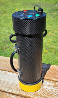
Surface materials are more durable than paint and the carbon fiber finish looks great!

UPDATE Mar 21 2013:  The BDAS-2 Antenna Launcher is currently out of stock. Production will resume in late April with units in stock during the first week of May. Please don't wait until the last moment - in the month before Field Day, I get overwhelmed with orders and you might not be able to get it in time.
Now up to Revision 2, with a new "Carbon Fiber Look". Pictures will follow, but this newly designed look is totally "Space Age" and has more clean and modern appearance. New materials were used and the finish is also more durable and less prone to wear and scratches than the old painted surface. The painted version will still be available upon special request at a slightly higher price. The Ramrod in Revision 2 is also updated - now the handle is made out of two parts with friction assembly for an improved portability and shorter storage length (not pictured above).
Lead times for new orders on "Out-of-Stock" products is 2 to 3 weeks. "In stock" items ship within 3 business days after the payment clears.
BDAS-2 Antenna Launcher  (current version) - $299
BDAS-1 Antenna Launcher (legacy) - Special Orders only (TBA)
Complete Kit Includes: Antenna Launcher, Zip Reel with 150 yards Leader Line, a set of 3 weighted projectiles (1x 6oz, 2x 4oz) and a Ramrod
BDAS-2 Antenna Launcher / "T-shirt Cannon" option - $249
"T-shirt Cannon" option - no Zip Reel, no Leader Line and no Projectile Set are included. A 2.5" coupler is included along with BDAS-2 Launcher and a Ramrod.
All orders ship via USPS Standard parcel service or UPS Ground- customer pays actual shipping fee for 26x13x8" box / 14 Lbs from Zip code 06804. Continental US only.
Local Pickup is also available at no additional charge.


My article on the Pneumatic Antenna Launcher generated huge amount of interest. A bunch of web sites like Hack-a-Day, Make Magazine, Wonder How To and others featured the article and increased the popularity even more. Since then, people are asking from assistance with building their own launchers to wanting to buy a finished product. I end up making a small production run to satisfy these needs. Field Day is coming and I am left with a few  launchers for sale from this run. I have not decided yet if I'll keep making them - the process is rather time consuming. If I decide to go on, I will likely create a separate web site.
These launchers are no-compromise, top-shelf product for people who demand high quality (and they look great too!). Ready to use - no assembly is required! Each kit includes a Launcher, a Zip Reel loaded with 150 yards of 50lb Test Hi-Vis Yellow Spectra Line, a Set of 3 projectiles (Weighted Tennis Balls - 2x 4 oz and one 6 oz) and a Ramrod. For more information, specs and details, please download the User Manual before ordering (for those who already purchased a launcher before 2013 - this is a revised  version of the manual - please download it and use it instead of the printed one included with the Launcher). Shipping to Continental US only! Price is set to $299 + actual shipping charge. For ordering, please email: ae1s AT arrl.net. Payments via PayPal or Cashier Check or cash for Local Pickup. Ships in 3 business days.

 "Graphite - Yellow", "Graphite - Orange" and "Steampunk"

"Steampunk" is the most popular finish people were asking for. Somebody even ordered one these to use as a "T-Shirt Cannon" for his band.

 Picture of the Trigger Valve Assembly

 Zip Reel with Leader Line.. A nifty Line Cutter is mounted on the bottom.

 The unique "Safety" feature in "ON" position 

 "Graphite - Orange" - The combination of metallic / graphite look and bright signal orange looks really nice.

 Another angle on the Trigger Valve and mounting bracket with the "Safety" Strap
Safety was a priority when building these launcher. Only pressure rated fittings were used - no drilling and epoxy gluing of PVC parts here. 

All launchers feature a Safety Relief Valve. Every single junction is Solvent Welded. The attention to detail is obvious everywhere you look. During painting, every part was carefully masked - note how the front face of pressure tank cap is painted and the clean edge between colors.

"Graphite Yellow"

Thursday, March 29, 2012

Yet another set of VNA calibration standards

This time - Type-N female. One of the most critical components in DIY calibration standard is the connector used to build it. The market is flooded with all kinds of connectors but most of them are of really shoddy quality (sorry to bash on China but that's where all the junk comes from). After playing with and testing different connectors, my conclusion is that one is shooting in the dark ordering connectors from China to use for DIY cal standards. Very rare there will be good enough connector from China, even for 60 MHz VNA cal standard. It is unbelievable the amount of sub-standard junk they make!
The best way to go about is to find high-quality brand name connectors on the surplus market. Ebay is also a good source but it takes time and patience to find what you need.
I've mentioned before that having a few sets of cal standard -different connector type and gender is very useful! I needed a good set of female Type-N OPEN and SHORT (I have a commercial LOAD).
One can buy on eBay a used female Type-N to female-SMA adapter of REALLY high quality for about $10/pc - I am talking about Amphenol 131-445 / HP-Agilent #1250-1404. Even at $30 this adapter is still a bargain. It is actually a bulkhead female Type-N used for commercial VNAs, Spectrum analyzer and other lab equipment. The body is machined from stainless steel, the pin receptacle is gold-plated copper-beryllium and it is using very interesting dielectric.
The center dielectric is made of a small plastic disc with 6 dead holes - 3 on each side of the disc. In each set the holes are at 120 degrees and the two sets are offset by 60 degrees from each other. As a result - the center pin receptacle is supported only by 6 very little plastic spokes. The holes are fairly large leaving mostly air around the center. This is as close as it gets to DIY air dielectric while still have strong mechanical support for the pin receptacle. I think the reason for the "dead holes" is to stop dust and contaminants getting inside.

For the OPEN I just cut the center pin flush to the dielectric. The dielectric disc has a brass sleeve in the center. A dab of solder fixes the pin receptacle to the sleeve. The disc is not made from teflon and soldering time and temperature should be minimal. One can easily measure the distance to the reference plane and calculate the offset. The stray capacitance and losses are minimal due to the dielectric's construction.
The SHORT is made by soldering a "washer" of tin-plated brass to the center pin. When the back shell (the gold plated part) of the connector is screwed in place it presses onto the outer part of the washer and makes the electrical connection to the connector's body. I left the rest of the center pin intact - it goes inside the teflon dielectric of the back SMA part for additional mechanical support.

Thursday, March 1, 2012

Crystal Test Fixture

Jack Smith, K8ZOA posted an interesting paper on "Measurement approaches of Crystal Motional Parameters" and designed a test fixture (based on the "classic" IEC 444 pub. fixture) to aid such measurements. The fixture is rather simple - it is comprised of two impedance matching attenuator pads, presenting the crystal resonator with a low, accurate impedance (12.5 Ohms, the center of the 5-20 ohm range of crystal's series resistance) during transmission measurements and transforming it from and to the 50 ohms impedance of the source and detector. These attenuators act as sort of a "buffer" - because of the transformation, the crystal "sees" only the accurate 12.5 Ohm input and output impedance regardless of the source's and detector's return loss.
Each attenuator is in Pi-pad configuration with attenuation of approx. ~15 dB (due to standard resistor values, the actual calculated attenuation for each pad is 14.81 dB). Input shunt is 158.0 Ohms, series resistor is 66.50 Ohms and Output shunt is 14.30 Ohm (ideal calculated value is 14.20) - all in 1206 packages 1% tolerance.
It occurred to me that Ivan Makarov's N2PK VNA Reflection Bridge PCB can be modified very easily to accommodate both pads and I can use the board to build the entire test fixture. The modification is very simple!

I used a Dremel Tool to drill (Carbide PCB drill bit #71, 0.0260") 3 holes (0.1" spacing) for the crystal socket / header and a small end mill bit to make to cut two trace cuts.

The socket is a gold-plated machined type - it can be cut from an IC machined socket. The HC-49 crystal package fits perfectly in the socket. An adapter can be made if the fixture is to be used with other components with larger diameter leads.
The socket is installed on the reverse (solid ground plane) side of the board. The middle pin is soldered to the ground plane on the component side. Copper is removed around the two side holes (on the socket side) so it will clear the bottom part of the socket pins. The ground plane should clear each socket pin by at least 1 mm around (the diameter of the no-copper area around each hole is about 0.1"). Again, a round end-mill bit or a big round engraving diamond file bit on the Dremel Tool will do the job.

This picture shows the configuration of the resistors in each Pi-pad. The ideal value for the output shunt is 14.2 ohms, so I installed 2.2k (1%) resistors in parallel with each 14.3 resistor to bring the resistance down. I used my LCR meter to select all attenuator resistors in order to have values as close as possible to the ideal calculated values. RF screen (cut from tin-plated brass sheet) is installed across the board, on the component side to shield the output from the input. The unnecessary PCB pads are flooded with solder and connected to the common ground plane.

Two edge mount SMA (f) are installed 2" apart. The 2" spacing matches my N2PK VNA port spacing so I can install the fixture directly on the VNA ports without the use of any cables.

Two copper-beryllium contact clips - one on each side of the socket are soldered to the ground plane. These spring clips connect the resonator's can to ground when the crystal is inserted and provide additional mechanical support for the crystal package.
The picture also shows the THRU calibration jumper and 50 ohm load test jumper.

Tuesday, February 21, 2012

Reflection Bridge with Type-N connectors

I always try to avoid using "between-series" adapters - there are so many out there with questionable quality. Sometimes these adapters are just the "necessary evil". In an attempt to reduce the need for adapters, I built 3 different reflection bridges for my N2PK VNA - BNC, SMA and Type-N.
From a mechanical point of view, mating a bridge directly onto 2 fixed distance ports presents a challenge - the connectors must be aligned perfectly. These are precision connectors and even the smallest misalignment will cause stress to the pin/receptacle, uneven wear and possibly damage. Using Type-N flange connectors on the reflection bridge will form too rigid junction and they are difficult to install with such great precision. On the other hand I prefer somewhat rigid connection and don't want to use flexible coax as it introduces phase instability when bent or twisted. A few tenths of the millimeter lateral "play" in the connectors will be enough to take care of small misalignment.
To build the Type-N bridge I used a pair of male Type-N connectors (solder type, Digikey p/n ACX1132-ND) on ~3 cm pieces of semi-rigid coax (RG-402 - solid copper tube shield, not the hand-conformable type). The coax is inserted in a brass tube (very slightly larger than the diameter of the coax, 2.1 cm length, K&S Engineering 3/16 x .014 Stock #129) that goes thru the wall of the aluminum enclosure and it is soldered inside to a brass plate. A second, larger diameter brass tube (2 cm length, K&S Engineering 7/32 Stcok #130) goes over the small diameter tube but does not go thru the wall. The small diameter tube provides stress-relief on pull action, as one end of the RG-402 is soldered to it. The larger diameter brass tube goes over the solder collar in the base of the male Type-N connector and it is compressed between the enclosure and connector, providing stress-relief on push action.
The whole assembly might be a little over-engineered but it is very sturdy and gives me the few tenths of millimeter lateral flexibility at the connector end without being too flexible. It, also protects the RG-402 from accidental permanent bending and damage.

The small diameter brass tube goes thru the wall and together with the protruding copper shield of the RG-402 coax is soldered to a brass plate and the PCB's ground plane. It is critical that the holes in the aluminum enclosure are just big enough for the small diameter brass tube to be inserted with no "play"as the flexibility needs to come from the exposed length of the brass tube. An SMA connector is installed for the DDS source termination (needed for improved low frequency measurements).

Heat-shrink tubing color-coded the IN and OUT of the reflection bridge. For the DUT port I installed a high-quality Amphenol 131-445 / HP-Agilent #1250-1404 female Type N connector. This instrument grade connector has a SMA(f) on the back. A corresponding SMA(m) with really short pigtail (~4-5 mm) was used for connection to the bridge. I had to make a cut-out in the PCB to accommodate the SMAs.

Because of the custom Type-N connectors, I was able to fit the bridge in a lower profile enclosure - same type I used for my RF-IV sensors - Bud Industries CN-5701 (Digikey p/n 377-1512-ND)

Tuesday, January 17, 2012

My 2nd Generation N2PK VNA

I am just about done with my second generation N2PK VNA. The first one I've built is mainly for portable / field use, while this larger unit is for my work bench.
Main differences over my first generation unit:
- built-in USB interface using HSUSB (both VNAs are based on the parallel port PCB ver. 4.3)
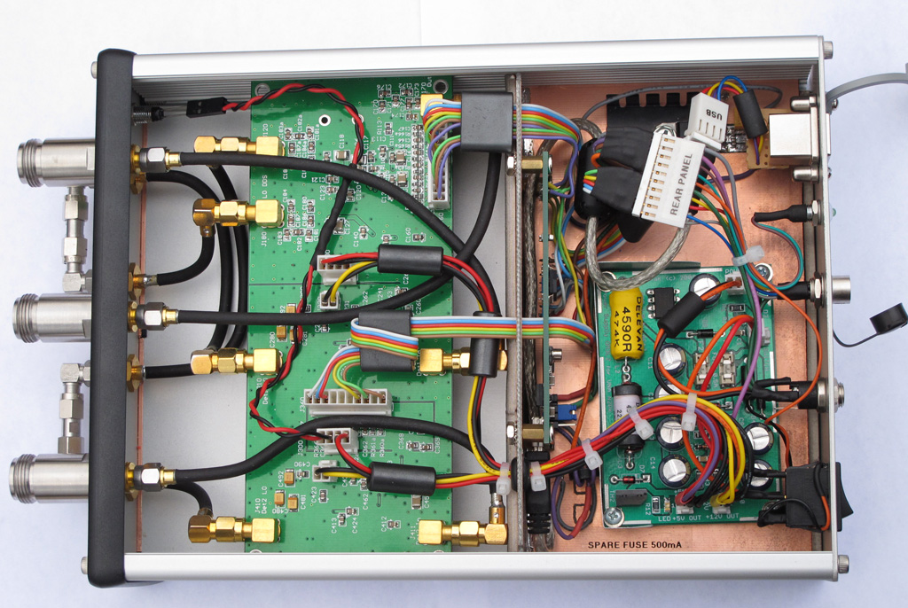
- larger enclosure with separate shielded RF deck compartment and PS/USB rear compartment (Hammond 1455T2201, Digi-Key p/n HM905-ND)
- Instrument grade, stainless steel precision Type-N and SMA front panel connectors (Amphenol 131-445 / HP-Agilent #1250-1404)
- All internal RF connections are made with Conformable semi-rigid RG-402 coax (Belden 1673A)

The larger enclosure provides better cooling and thermal stability. I have separated the space into two compartments in order to improve the RF shielding and noise floor. Furthermore, the use of semi-rigid coax requires more space. I must say that working with semi-rigid coax is not an easy thing, even when using hand-conformable type. The connections must be fabricated with a great precision, avoiding re-bending of the coax. I used scrap pieces coax to get the right shape of each link and then carefully followed the shape with the actual coax, bending it only once.

The front panel is using very-high quality lab-grade (read: very expensive) RF connectors. I also improved on the front panel layout. A front panel LED indicates +5V power to the DDS chips.

The rear panel with industrial grade Type-B USB connector. The LED next to the connector indicates power to the USB interface. The USB interface board can be powered by the host computer or by the internal power supply (jumper selectable). I also made a small modification to the HSUSB board to incorporate the VNA PWR DETECT signal directly on the board itself. An Accessory connector is installed for connecting the S-parameter test set, RF-IV test head or any of the two transverters. It is a 6 pin connector with all necessary control signals and +9V power for the accessories.

The power supply mounting bed. The N2PK VNA power supply provides +5v (using a switching regulator), +9V and +12V (linear regulators). There are "crowbar" type over-voltage protections for both, the +5 and +12 V as well as extensive filtering and power conditioning. This picture is with the top RF shield of the PS board removed. The HSUSB board is mounted vertically using stand-offs, on the back wall of the RF compartment shield. The linear regulator and heatsink next to the PS board is for +9V line going to the ACC connector.


The PS mount was constructed by soldering two pieces of copper-clad FR4 PCB material.
On the bottom I mounted copper-beryllium contact clips for better grounding to the aluminum enclosure. When installed, it is a tight fit in the aluminum enclosure, effectively shielding the VNA board from the switching PS and USB interface board. Using such mount, I was able to install everything in the enclosure without drilling any holes and using external screws - it is pure aesthetics but the VNA does look sharp that way.

The noise floor of Detector 1 is slightly better than -120 dB for the most part (0.05 to 30 MHz it is about -122 dB).

In addition, I made a reflection bridge using SMA ports and SMA-to-N adapters. Initially, I was going to built it with flange Type-N connectors but these are more involved (5 holes, 4 screws each) to install and the Bridge becomes too "rigid" while being mounted on the VNA ports. The bulkhead type SMA (f) requires just a single D-hole to install and in general the SMA port gives more flexibility. The SMA connector is not the optimal solution for heavy front panel use but this is not the case as the SMA(m) to male Type-N adapters will be almost permanently installed. I soldered the back of each SMA to a brass strip for improved grounding to the chassis and PCB. An additional SMA (f) connector for low impedance termination (used for measurements below 0.5 MHz) was also installed and connected with a short pigtail of RG-405.

I used a stainless steel, heavy duty SMA on the DUT side as it will see more connect-disconnect cycles than the VNA side SMAs but it required a cutout in the PCB and a small brass plate to solder the ground plane.

Tuesday, November 22, 2011

Experimental Parabolic Microphone

I've always wondered how well a parabolic mic works. Here is my experimental setup for testing such DIY parabolic microphone. It is a great weekend project and will let me experiment with high-gain / low-noise audio amplifiers. The heavily wooded area off my back yard is plentiful of singing birds.


Photographic tripod is used as mount for the parabolic dish. I had to construct a simple mounting bracket and a "focusing" contraption that will let me use different size and shape microphone elements.

I got the actual parabolic reflector from "the place where you can find anything" - eBay. The parabolic reflector is made out of polyethylene plastic. The diameter is 21 inches with focus point 4 inches from the bottom. It came as one solid reflector - I had to drill the mounting hole. I had a few ideas for mounting the dish - I wanted to be compact and simple so I decided on a single hole in the center.

The microphone mounting frame is made from semi-rigid coax (RG-402) and small PCB board for attaching the mic element. I used a threaded cable feed-thru to both - attach the dish to the bracket and mount the RG-402 frame with the microphone. A "sandwich" of metal and rubber washers - including two large and thick rubber washers provides "shock-mount" for the dish. The mic frame is fed through the threaded feed-thru using silicone cemented inserts.

The "focusing" rig lets me move the microphone element to the exact focus point of the dish. The focusing range is about 2 inches. Normally, the mic can be fixed in the focus of the parabola, but I am planing to experiment with different mic elements and they all vary in size and shape so I wanted to be able to adjust the mic frame with no hassle. Two spring-tensioned wing nuts fine-tune the mic frame.

Small plastic container is holding the battery pack, microphone preamp and 900 MHz FM transmitter (a.k.a Baby Monitor - For the initial testing and to validate the concept I just modified a baby monitor and then used my IC-R20 scanner to listen and record). Currently, I am working on my low-noise/high-gain preamp. The radio-channel link sort of works but the noise levels are way too high. Proper mic pre-amp and better (broadcast grade) FM transmitter are planned for the next stage.

Hand-held mode. Large plastic handle salvaged from old angle-cutter provides comfortable grip.
A word of warning - the surface reflectivity of the polyethylene dish is high enough to produce smoke from the mic's wind guard while I was playing with the dish and decided to verify the focus by pointing it at the sun. It took less than a second! I was able to act quickly and saved the guard from catching on fire :) (stupid move but the damn thing looks transparent :-)