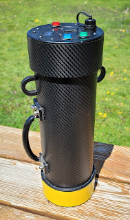
Tony Montana's famous words as the answer to the question: How do you get an antenna rope over a 100+ ft tree-top? Forget about slingshots or bow and arrows. Even the crossbow with optical sight is so last century :). Enter: the pneumatic antenna launcher or shall I say "pneumatic blunderbuss";-)
 Here is the result of a couple of evenings spent in the garage - cutting, gluing and painting PVC pipes.
This antenna launcher is based on (WB6ZQZ) Alan Biocca's CSV19 with some modifications / improvements on my part. His web site (http://www.antennalaunchers.com/) is an excellent source of information on these launchers and it has very detailed build instructions. I had to do something about the white PVC look which I REALLY hate! The paint job was inspired by K4ICY and his "Steampunk" antenna launcher.
The main changes from Alan's CSV19 design are:
- Slightly larger compressed air tank - my launcher is using 10 inch length of the 4" diameter pipe for the tank vs. Alan's 8 inches. The reducing coupler I am using as part of the tank gives a little extra volume too.
- Longer barrel - 18.5 inches vs. Alan's 16 inch barrel - I had lengthen the barrel a bit in order to account for the larger pressure vessel and have enough clearance for the Zip Reel.
-More reliable and safer pressure vessel - instead of drilling a hole for 1" pipe and epoxy gluing the pipe for the high pressure outlet in a 4" end cap, I am using a 4" to 2" reducing coupler and then 2" to 1" reducing bushing as part of my pressure vessel. Another advantage is that I don't have to drill precision large diameter hole - unfortunately I don't have a lathe.
-More reliable and safe coupling between the barrel and the high-pressure pipe - I am using 2.5" to 2" reducing coupler and 2" to 1.25" inch reducing bushing. It is much easier to assemble the launcher that way! Alan's design yields for drilling a 2.5" end cap and epoxying the 1.25" inlet (actually, a 90 degree elbow) in the hole
-I made the spacer between the pressure tank and the barrel out of two pieces PVC, sliced from 4" pipe scrap. I adjusted the curvature of each piece to follow the outside diameter of the corresponding pipe and glued the pieces back-to-back.
-In a moment of sheer brilliance, I came up with the Augmented Reality Digital Scope. The HUD (Head-Up Display) on the scope shows the firing angle of the barrel (pitch), heading, roll, and geographical coordinates. It is also capable of measuring distance and most importantly height of an object (tree). (Scope is not shown on the picture above)This is probably the most significant improvement to the launching system I am willing to take credit for as it allows to correct your shots in a precise manner by adjusting the exact angle of launching. About the only thing I am missing is on-screen display of the air pressure in the tank. More on this in a later post...
The main source of PVC hardware for this project was http://flexpvc.com/. Trigger, pressure gauge and Schrader valve are available from McMaster (the trigger is part 6852K11). Rainbird 100DV-SS sprinkler valve is from eBay. The bow-fishing zip reel is from an online archery store. Brass fittings, brass street elbow and aluminum stock (for the Zip reel mount and support strut) - all from Home Depot. Tennis balls and Spectra line (150 yards spool / 50 lb test) from Sports Authority. For all threaded connections (sprinkler valve to trigger valve, pressure gauge, Schrader valve) one should use the yellow type Teflon tape - it is made specifically for gas/high-pressure applications and seals much better than the standard white plumber's tape. I hated the rattling sound of the coins (used to bring the weight to 4 oz) inside the tennis balls so I injected the balls with polyurethane foam (used to fill gaps). For the tennis ball tie, I used a loop of string with a knot, drilled a penny right in the center and inserted the loop thru the hole. The knot should be large enough so it cant go through the hole. Then I inserted the penny vertically in the tennis ball thru the narrow slit I previously made. When I pull on the loop, the penny wedges flat across the slit - this solution works just fine and after I filled the ball with foam there was no need to stitch the slit - the foam glued the slit and the pennies inside.

This picture shows the installation of the Saunders Bowfishing Zip Reel. Two aluminum bars are attached to the zip reel and the 2.5" coupler is mounted in the center with countersunk screws. (the bottom side of the coupler was filed flat to form two "saddles" for the mounting bars). It is loaded with 150 yards of high-visibility Spectra-Line (50lb test). I even installed a little cutting blade (the yellow thing on the bottom) for added convenience. This line cutter was part of the Spectra Line packaging - i just had to cut it out from the plastic spool-holder.
Update: In the original design the trigger valve could loosen or over-tighten if one is not careful - the valve is not fixed - it relies entirely on the thread and because it must not go all the way in (the street elbow is just partially threaded, 2-3 turns max), accidentally rotating the valve in either direction could cause a variety of unwanted effects.

Alan, WB6ZQZ suggested to use a strut to support the trigger so this is what I came up with. Small piece of curved PVC (scrap 4" pipe, heat gun, 2.5" pipe used as a form for bending and sanding) is drilled for a countersunk screw then glued to the barrel with the screw in place to create an anchor point. An aluminum bar is used as a strut between the anchor point and a brass trigger outlet extension. The red cable-tie is the "safety" (currently in ON position) - it prevents accidental operation of the trigger.
Another solution for the strut anchor point is to drill, countersink and install the screw from inside of the 2.5" to 2" coupler BEFORE the 2.5" barrel pipe is glued. The hole for the screw should be drilled in the middle (or closer to the edge) of the 2.5" portion of the coupler and the countersinking should be deep enough to allow for smooth installation of the barrel after the screw is inserted. There is not much clearance for right-angle drill -the countersink can be done with RA Dremel attachment or manually by hand.


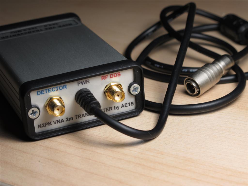


 The main reason for matching the calibration reference plane and the mating plane of the VNA test port connector is to allow industrial VNAs to measure whole assemblies and devices, including their connectors. In the N2PK VNA (at least with the original software) the reference plane is assumed to be where the physical OSL calibration takes place. Instead of adding negative offset to move the reference plane back to the mating surface of the VNA's test port connector, it is accepted that the plane is right at the rear surface of the calibration standard connector (the location of the actual Open-Short-Load). The error introduced by the electrical length of the pin inside the connector is not that great at lower frequencies - for instance, assuming teflon dielectric (VF ~70%) in a standard SMA connector used for a home-brewed calibration standard, an offset of 5 mm will yield about 0.5 degree phase error @60 MHz. Commercial calibration standards use air dielectric, but this puts greater mechanical requirements during the fabrication process. By calibrating the VNA so the reference plane is on the back of the cal connector and fully exposed, it is more convenient to measure a single component but it means that the DUT test fixture should be made of (or at least include) the same type connector as the one used for the home-brewed calibration standards in order to maximize the accuracy. The setup can be as simple as the component (DUT) is just soldered on the back of the "test fixture" connector, while measures are taken to minimize external error (minimal lead length). With SMDs, this approach works well as the device is practically located directly at the "reference plane" when the test fixture connector is from the same batch connectors used to make the OSL standards. Another method for calibration is to use the test fixture connector itself for calibration - for OPEN the DUT is simply omitted, SHORT and LOAD are created on the spot during each calibration step and finally the DUT is soldered (Still, stray C for the OPEN must be known)