Showing posts with label Gamma Dog. Show all posts

Monday, September 23, 2024

Gamma Dog - Rate-to-Tone conversion and Audio Frequency Modifier

One of Gamma Dog's unique features is the continuously variable tone representing the detected count rate by changing its frequency.

The approach is fairly straight forward - the detected count rate in CPS (Counts-per-second) coming out of the detector and into the MCU is converted into an audio tone with the same frequency - i.e. 200 CPS will produce 200Hz tone and 1000 CPS will produce 1 kHz tone. 

Due to a lucky coincidence, the detectors we use, especially the 63mm NaI(Tl) crystals produce around 180 - 230 CPS for average background levels which is a really good starting point thus the overall detector sensitivity and rate response work very well with such direct conversion method.

As the count rate increases though, the tone frequency will increase, and this could become a problem at some point when the count rate becomes really high (above 7000 - 8000 CPS) - nobody likes these very high pitch audio frequencies (certainly not the dogs and the mine bats :-) - such high pitch is not the most pleasant thing to listen to. Not to mention that it becomes quite difficult to hear small variations in the frequency within this high frequency range.

To combat this problem, the "classic" version of the Gamma Dog always starts the frequency generation at the set squelch level - this way if Squelch is set to 7000 CPS, and detected rate is around 7000 CPS the tone frequency will be low - less than a hundred Hertz (whatever difference is needed to break through the Squelch Threshold) , opposed to a 7 kHz tone.

In my Gamma Dog+, the system for rate-to-tone conversion is further enhanced and offers to the user a toolset of numerous conversion options. These options afford greater control over how the Frequency Audio Response to the Count Rate conversion is taking place, customizing it for different applications and listening preferences. 

The "xL" indicates Logarithmic Scale conversion (selectable when in Continuously Open Squelch Mode / "#" by using the Soft Key) 

Changes in the conversion model are done via a user-selectable option that can be assigned to the Soft-Key button. It is called Audio Frequency Modifier or AFM for short. 

In a nutshell, AFM (in some of the options) is a Multiplication Factor that is applied to the count rate while converted to tone:

There is a total of 8 options: x0.5, x1 (default), x1.25, x1.5, x2, Auto, Exp and Log

The first few options are self-explanatory - if x0.5 is selected, the rate is divided by 2 before it determines the frequency of the tone - i.e. 200 CPS rate will produce 100Hz tone, 210 CPS will produce 105 Hz and so forth. It halves the base frequency but also the steps between changes. On the other end, with x2 selected, 200 CPS will produce a 400 Hz tone and 210 CPS will produce a 420 Hz tone. The default value of x1 is the direct 1:1 conversion.

The x0.5 option for example, is useful with very large detectors to keep the audio frequency output low against the natural high-count rate of the detector, while x2 is useful with smaller detectors which natively produce fewer counts, and the option allows to keep the tone frequency higher than a direct 1:1 conversion in this case.

In Auto mode the multiplication factor is based on the Detected Rate increase over the Squelch Threshold Level. The audio frequency modifier is dynamically adjusted in 4 steps based on the delta between the two rates.

If Current Rate exceeds Squelch Rate by more than 175% - Frequency Multiplier x2.5 is used.

If Current Rate exceeds Squelch Rate by more than 150% - Frequency Multiplier x2 is used.

If Current Rate exceeds Squelch Rate by more than 125% - Frequency Multiplier x1.5 is used.

If Current Rate exceeds Squelch Rate by less than 125% - Frequency Multiplier x1 .25 is used.

This feature will change automatically through different multiplier levels while using the squelch level as control of where the "step-ups" should take place.

This graph plots how the frequency conversion steps through the multiplication range using the difference between detected rate and the set squelch rate. As the squelch opens and the rate continues to climb, the multiplier will start stepping up, increasing the audio frequency.

There are also two non-linear conversion modes available - Exponential and Logarithmic.

Exponential Mode – The audio tone frequency will increase in an exponential manner, with a scale factor of 0.0033 and base frequency of 100Hz using (e) Euler's Number.

This feature is independent of the Squelch Level - the squelch just needs to open but otherwise has no effect on the conversion. 

It is usable with absolute rates up to 1400 CPS.  Beyond 1400 CPS the audio frequency will exceed 10kHz!

Exponential mode is useful to detect very small increases in the count rate when the absolute rate is also very low. For example, in very low activity areas where small rate changes need to be detected - the audio tone frequency is exponentially increased, exaggerating the tiny rate variations by using higher pitch tones.

Logarithmic Mode – The audio tone frequency will change on a Logarithmic scale – the range of 40 CPS to 10K CPS will be "compressed" and mapped by using a logarithmic curve to an audio range of 40Hz to 3kHz.

This feature, just like Exp Mode is independent of the Squelch Level from Rate-To-Frequency standpoint, and it provides very good audio resolution for lower count rates (<2000 CPS), while still capable of handling very high count-rates (2K to10K+ CPS) - all within a narrower 3kHz audio range.


The range between 2000 CPS and 10000 CPS is allocated within less than 1kHz audio frequency response (from ~2200 kHz to 3000 kHz) which is useful when the instrument is used with both, very low and very high-count rates. This comes at the expense of audio resolution in the high-count region of the curve and overall higher frequency tone at the mid-low count range.

In the Gamma Dog's menu system, there is a config item (#10) which allows the user to select a startup mode for the Audio Frequency Modifier, but the mode can always be changed later, during operation, if "Multiplier" is assigned to the Soft Key button in Menu Item #8.
(The other assignable function to the Soft Key button is control for the Audio Conversion Hysteresis Level responsible for how closely variations of the rate are followed before converted to audio tone)  

Friday, November 3, 2023

Gamma Dog - Assisted Squelch Auto-Set (ASAS) / "Smart Squelch" System

One of the main features of the Gamma Dog project is the unique Squelch System controlling the audio output.
Anyone familiar with two-way radios will be familiar with the Squelch System used in FM Hand-Held Transceivers.
In a nutshell, Gamma Dog's Squelch System mutes the audio output of the instrument if the currently detected rate is at or around the natural radiation background level. If the rate goes up, above the background level (in the presence of a radioactive specimen for example), the Squelch System enables the audio output of the instrument and a tone with variable pitch is produced. Once the rate drops back to background level or below, the squelch closes and the audio is again silenced.

This post will delve deeper into the inner workings of the Squelch algorithm and the Assisted Squelch Auto-Set (ASAS) System.

Before we get to the boring plots, here is something more amusing - here is AI's idea of what "Gamma Dog" is.

The Gamma Dog's Squelch System works by detecting a differential between the Natural Radiation Background (NRB) and the current detected rate coming from the scintillating detector. The Squelch System evaluates the Natural Background, mutes the audio and sets a threshold level at almost the same rate as the NRB. When the currently detected rate exceeds this threshold level, the audio output is enabled.

In other words, the current rate is treated as a relative rate to a pre-set reference point (the Squelch Level) and the absolute value is insignificant for the Squelch System.

I am saying "almost the same as the NRB" because establishing the optimal level (rate) for the Squelch system at any given moment is a bit tricky due to the randomness of radioactive decay and the constantly changing conditions during prospecting.

Gamma Dog will sample the NRB rate on startup or any time when the Assisted Squelch System or the user activates an "Auto-Set" action (by pressing and holding the blue Squelch button or using one the Pose-detection triggers).

The term "Auto-Set" comes from the fact that the Squelch Level (rate) is established automatically, based on sampling of the current rate. This is always done on startup, but later a Manual Set can be done by the user, overriding the established level and setting it to a different value.
 
When "Auto-Set" is activated, Gamma Dog will use one of 3 available methods to determine the Squelch Level (the method used is selected by Menu Item #1):

    1. SS (Single Sample) - Squelch Level will be set to the currently detected rate, using a single sample at the moment when Auto-Set action is triggered.

    2. SD5 (default) - The Gamma Dog will average the rate over the last 5 seconds, calculate the Standard Deviation in the rate and then use the upper bound of the 1-sigma threshold to compute and set the Squelch Level.

    3. SD10 - same exact method as SD5 but the rate is evaluated over the last 10 seconds before Standard Deviation is calculated.
 
The 1-Sigma Upper Threshold is calculated simply by summing the mean rate over 5 or 10 seconds and the Standard Deviation of all samples taken in the data set. 

The horizontal purple line is the Squelch Level as result of a Single Sample (S-S Mode).
The orange line shows the actual current rate, and the blue line shows the smoothed rate.
It is obvious that the Squelch level is set too close to the mean rate and the current rate deviates too often above it, opening the Squelch System.
 Another problem that can arise from this method - in some cases (purely random), it can cause the Squelch to be set too low or too high as it relies on a single rate sample in time and if this sample happens to be a random peak in the rate or a deep valley, the squelch level will be off.

In SD5 mode, the Squelch Level is set to the upper bound of 1-Sigma of the Standard Deviation, evaluated for the past 5 seconds (data set includes a history of 5 samples done at 1 sample per second).
 This is the Gamma Dog's default method. It does a much better job at finding the correct Squelch Level while the system responds better to quick rate changes due to the short rate history being evaluated.

The last available option - SD10, is the same as SD5 but the evaluation of the Standard Deviation is done for the count rate over the last 10 seconds. 
It is the most precise way to find the correct Squelch level and results in very minimal number of excursions of the Current Rate above the Squelch Level but due to the longer history of rate samples in the data set, it is less "dynamic."

Note: The plots above were made using the Gamma Dog's Bluetooth functionality - all of the data displayed on these plots was sent in real-time via BT to a companion Android App and plotted there. 
The yellow line at the bottom of each plot shows the current battery capacity in percent.

As discussed above, critical aspect to the operation of the instrument is a properly set Squelch Level - the audio is used to alert the user of an anomaly in the detected rate.  When the level is correctly set, it will make the squelch system responsive to small fluctuations detected just above the background level. The level should exclude or rather - "minimize" the effect of fluctuations of the rate due to the randomness of radioactive decay.

Why I calculate Standard Deviation and not just "pad" the mean rate with a fixed value? 
The answer is simple - "padding" or offsetting the level from the mean rate can cause inaccuracies because the deviation from the mean rate varies with the isotopic content, distribution of radioactive material, detector sensitivity, etc.

For U and Th isotopes with extremely long half-lives as well as other decay-chain products, which makeup good part of the Natural Background, the distribution of decay events over a very short period of time (5-10 sec) can be reasonably approximated by a normal distribution, although the actual distribution is still governed by the exponential decay law.

In my testing, assuming normal distribution of the decay events and using 1-sigma of the Standard deviation works very well for figuring out a good and reliable Squelch Level.

From a practical point, the "sweet spot" of the squelch level is when the current natural background rate (NRB) only occasionally opens up the Squelch System but not too often - up to 3-4 times per minute or less is a good level. 
These Squelch opening events indicate to the user that the level is very close to the optimal one by the occasional breaks in the silence.

The Squelch level can be Auto-Set (by sampling the Natural Radiation Background rate) or adjusted Manually, when the user is modifying the already set level with the GD Squelch Level +/- controls.
In either case, if the Squelch Level is incorrectly set against the NRB level, this could result in missing possible specimen finds or less-than-optimal Squelch performance. 

Let's make it Intelligent!

One of the problems Charles and I encountered in the field while surveying and prospecting different areas is the Squelch response to highly localized Natural Radiation Background Levels.

For example, when surveying a REE deposit in Southern New Mexico we realized that the NRB is extremely localized to the terrain - there are very well-defined areas of the pegmatite exhibiting very high Natural Radiation Background ("hot zones") and just a few yards away, other areas with comparatively very low NRB ("cold zones"). Some of these "cold zones" exhibit natural background even lower than what is considered "normal" for the general area! 
Such contrast and localization posed a unique challenge - it meant that we had to constantly sample the NRB rate and activate "Auto-Set" of the Squelch system manually, every time we crossed over from one zone type to another. 
On the other hand, to know that you have crossed over to a different zone you had to monitor constantly the displayed rate - something I didn't want to do all the time. With Charles's version of the Gamma Dog, it was even more difficult due to the lack of display.
It is also worth noting that both zones in this pegmatite produced very nice Euxenite crystals which can be easily missed if the squelch level is not correctly set. 

In a situation of such mineral deposits, if we focus only on moving through the terrain without paying attention at the current Squelch Level, we can enter an area where the NRB rate is much lower than Squelch Level and any small peaks or fluctuations, possibly indicating the presence of a specimen, will be masked and hidden by the rate gap in the Squelch System (that is if the rate is not promptly re-adjusted by the user). 
It even could be some time, before one realizes that the instrument has been silent for too long due to a Squelch rate set too high for the current NRB Level.

The opposite is also true - crossing from an area with low background rate to an area with high NRB will cause the Squelch system to stay constantly open which defeats the purpose of having it in first place and it will require the user to activate the "Auto-Set" manually.

To resolve this issue, we came up with the "Smart Squelch" or Assisted Squelch Auto-Set (ASAS) System.

Assisted Squelch Auto-Set System

The purpose of ASAS is to constantly monitor the current rate, compare it to the state of the Squelch System and detect conditions which can indicate that the Squelch rate might be incorrectly set for the current background. 
Once ASAS determines that the Squelch Level needs an adjustment, it will trigger an Auto-Set action, same as if the user pressed the Auto-Set button and it will re-sample and evaluate the NRB.
This allows for very easy, smooth and worry-free operation - ASAS does all of the monitoring and performs the necessary adjustments as they are needed, allowing the user can focus on the terrain and not on the instrument. 

Note: The implementation of ASAS is different between the one I designed, and the one Charles is using in his GD version. The main difference is the algorithm and the fact that in my version, due to the availability of display, menu system and persistent configuration parameters, I can configure many internal aspects of the ASAS behavior and make it more flexible and more customizable for a particular situation.

These plots show how ASAS monitors the state of the Squelch System.
Out of the 21 Configuration Menu Items, there are 4 menu items dedicated exclusively to the ASAS system.

In my algorithm design, there are 2 separate timers configured with a single menu item, setting the period for a squelch condition to be present continuously, before an Auto-Set is triggered.
One timer is reset every time the Squelch opens, while the other timer is reset every time the Squelch closes. 
Basically, I continuously monitor the state of the Squelch System over time while constantly cross-reference the state with the currently detected rate and if a discrepancy is present for longer than the configured "time window", an action is taken.
The timers can be set for 15, 30, 45 or 60 seconds.

One additional functionality I implemented in ASAS is the ability to "decide" if Squelch Auto-Set is needed while the squelch has been open for a long time.
When the user needs to pinpoint the location of a specimen, it helps for the squelch to stay open so variations in the pitch of the audio tone can be closely monitored. In such case Auto-Set should not be triggered.

In my implementation of ASAS, I have a menu item which specifies a second, higher virtual threshold level which, when exceeded, it will prevent the Auto-Set from activating due to continuously open squelch event. This is done internally by resetting the Open Squelch Timer.

The logic behind this is that if a specimen is found and the user is now trying to localize it, the overall detected rate will be vastly higher than the NRB / Squelch Rate and not just slightly above it as expected - the ASAS system will identify this large difference in rates and it will not trigger an Auto-Set if the rate is sustained above the second threshold, thus allowing the user to listen to the audio tone without an interruption by a Squelch Set event.

The "ASAS Reset Lvl" Menu Item, determines the height of the virtual "localization rate" as a percent of the current rate above the squelch rate. This value can be configured as 37%, 50%, 62%, 75%, 100% and 150%.

For example - if ASAS Reset Lvl is set to 100%, the Squelch Rate is set to 200 CPS and the detector reports a current rate of >400 CPS (or exceeding the Squelch rate by more than 100%), ASAS will not trigger an Auto-Set assuming the user has found a specimen and just tries to pinpoint it. If the rate drops below 400CPS then the continuously open squelch condition will trigger an Auto-Set when the timer for it expires.

Another functionality in my ASAS System is the ability to add a "padding" (called ASAS Tolerance) between Squelch level and Current Detected Rate, while the squelch is monitored for continuously closed condition. The amount of padding or tolerance is adjustable with a menu item ("ASql Toler") and specifies in CPS how low the current detected rate must drop below the Squelch Level before the timer of the continuously closed squelch activates an Auto-Set action.
This differential can be set from just below the current Squelch Level to a few hundred CPS lower and it is intended to add "adjustable damper" for the response to constantly closed squelch.
The options are "Minimum", 100 CPS, 150 CPS, 200 CPS, 250 CPS and 500 CPS

By default, when the Gamma Dog starts, the ASAS is deactivated and can be toggled ON/OFF by double-clicking the GREEN Button.
The last menu item of the ASAS System configures whether the system is activated automatically at the startup of the instrument, or the user will activate it at a later time.

The ASAS System in action. 
In this video, I simulate "wrong squelch setting" by manually overriding the established Squelch Level while ASAS is active, and the level is set too low and then too high. ASAS responds by issuing a corrective action.

When the ASAS is active, the "Sql" indicator above the Squelch Level is replaced with "(A)".
The ASAS timeout is set to 15 seconds in this demonstration.

The two separator bars on the display (above and below the rate readout) shrink, showing when one of the timers is about to expire. The top bar is for Open Squelch conditions and the bottom bar is for Closed Squelch conditions. 
A full width bar represents the maximum duration the timer is set to, and the bar will shrink to a dot in the center (the trigger point, if conditions for adjustments are still present). 
At the moment of the Auto-Set event, a short beep is produced to indicate that ASAS has taken an action.
If a condition (a change in the detected rate) changes the state of the Squelch System, the bars reset back to full width and will start the timers again. 


Charles searching for REE in Petaca, NM while using the "Smart Squelch" System.
The Gamma Dog produces distinctive beeps every time when the Automatic Squelch System is triggered to re-sample the Squelch level ("Auto-Set").

UPDATE:
A more extreme rockhounding in Petaca, NM by Charles in March, 2024

Saturday, July 15, 2023

Gamma Dog hardware - PCB v4.0

I finished the design of PCB v4.0 for the Gamma Dog and OSH Park service came through again with excellent manufacturing quality boards.

The improvements in the schematics and layout are not huge but this version incorporates the progress in the development, which continued after PCB v3.0.

Gamma Dog Main PCB v4.0

Bottom layer with a Marie Curie quote.

Changes from PCB version 3.0:

  • Changed the placement of the DAC board and EEPROM board connectors. The new version of the 12-bit DAC daughterboard is slightly larger due to additional QT connectors and it wouldn't fit in the old footprint. 
  • Added HV voltmeter circuitry for measuring and adjusting the HV PMT Bias in the field - the measurement range is 0 - 1255V (max). The High-Voltage reading is displayed when entering the menu system's diagnostic screen and will allow for field adjustments when changing different detectors. The circuit provides also HV PS status data for the Self-Diagnostics / Health-Check during startup. The accuracy is better than the on-screen resolution of 1V.
  • Added the I2C digital potentiometer for the Digital Audio Volume Control to the main board (MSOP-10 package) - with the previous version it was an in-line add-on board as this feature was developed after fabrication of PCB v3.0
  • Added support for the LED in the GREEN/DOWN button - this LED now serves as "Charging" (flashing) and "Charge complete!" (solid) indicator during the internal battery charging.
  • Added an SMD jumper allowing the user to configure the power source for the Audio Power Amplifier module - options now are either the regulated 3.3V from the MCU board or the direct battery power (4.1V max) (affording the highest possible audio volume).
  • Re-organized (separated) and moved the DOWN Button and Audio Amplifier connectors - the GREEN/DOWN button now has a dedicated 3-pin connector (previously, it was shared with the Audio Power Amplifier), and the connector is placed right next to the BLUE/UP button connector, closer to the button's location.
  • Removed all of the unnecessary and unused component footprints, related to the old analog circuit for setting Minimum Pulse Height Threshold with a trimmer-pot.
  • Improved the matching between the motherboard's pads and the corresponding HV PS module Output and GND pads for easier installation of the piggybacked PS module.
  • Various small changes in component placement, trace routing and overall layout optimizations.

The Motherboard PCB with SMDs, sockets, headers and connectors installed. Visible, on the top-right is the HV voltmeter's VD string of precision resistors. 
The input impedance of the voltmeter is >1 GOhm in order to reduce any voltage drop caused by the measuring circuit.

Second Level of boards.
DAC, EEPROM and HV Power Supply + Pulse Amplifier.

Third level. 
The nRF52840 MCU module along with various sensors and RFI Shielding Can installed around the HV circuit.

Fourth Level completes the board stack.
Latching Relay module and RFI shielding cover installed.

Calibrated and tested V4 boards ready for the housings.

The official Firmware version is now v4.5, supporting the new hardware features and changes the way how unit-specific data is handled. 
The unique "Identity data" of each Gamma Dog unit, such as calibration offsets for various voltage dividers, pulse amplifier DC bias value, exact DAC reference voltage, serial number, etc is now stored in a dedicated "Read-Only" area of the EEPROM and not hard-coded in the firmware as it was before. 
Each unit is flashed with its "identity" during manufacturing, removing the need for unit-specific firmware code and simplifying development and future firmware updates.

New feature in the V4 hardware - High-Voltage Digital Meter - 0V to 1255V.
The PMT Bias reading is shown when entering the menu system. 
The value is constantly measured and displayed at a rate of 4Hz until a button is pressed. 
Adjusting the detector voltage in the field only requires a small screwdriver.

"Behind the scenes" - the machining work of the front panel. 
A 1/4" thick Plexiglas bezel for the display is already glued with black RTV sealant inside the display opening. The edge of the bezel is painted black to reduce internal reflections of the edge.
The display board is attached with self-tapping screws in blind holes. The blind holes for the audio boards are threaded and the board is secured with 5mm nylon stand-offs and 2.5mm nylon screws.

This picture shows all of the UI components and interconnects installed on the Control Panel. 
The wiring is done with JST connectors for a quick, easy, and clean assembly / disassembly.

The main board is mounted on brass stand-offs and connected to the Control Panel's UI components.
 There are only two connectors beyond this point - the white LIPO battery pack connector seen in the lower-right corner and the female BNC connector for the scintillating detector, seen just to the left of the battery connector cable.

The Complete electronics package of Gamma Dog V4. 
As a finishing touch, a 3D-printed bezel for the speaker opening retains a piece of open-cell foam to protect the speaker from dust and debris. Under the foam there is a second, fine metal speaker grill for mechanical protection.
Another cosmetic change in the V4 enclosure is a change in the way, the display and speaker board are mounted on the control panel. I used blind screw-holes from the back side to avoid exposed screw-heads on the front and the look now is nice and clean. The only screw-heads visible are the ones holding the main board. 
A self-diagnostics routine is executed on startup - the very first stage (pictured) is the check of all UI components.

Menu System in firmware version 4.5. In this video the Bluetooth connectivity is disabled, and the menu list skips the two BT-related items. Total of 20 Menu Items.

 At this point, I consider the firmware to be "fully matured" and bug-free.

Tuesday, October 18, 2022

Gamma Dog - Volume Control

One thing that was really bugging me with the Gamma Dog circuit was the original analog audio volume adjustment. 

The MCU swings a digital output pin, driving the amplifier input between 0V and 3.3V. This output is connected directly to a linear (class D) 1W audio amplifier which employs a tiny trimmer-potentiometer for gain adjustment.

To adjust the audio level in the field, first I have to remove the screw plugging the adjustment access hole (everything on the front panel is dust-proof) and then use a small flathead screwdriver to turn the internal trimmer-pot - hardly a convenient thing to do every time I needed to change the volume.

I normally keep the audio level pretty loud (3/4 of full power) as it helps during windy conditions but when it is quiet and one is kneeling right in front of the instrument, digging a hole or trying to pinpoint specimens, the loud tone in your face can get a bit annoying. Sometimes there will be a couple of us using Gamma Dogs near each-other and becomes a pretty loud "concert" so quick volume control is a "plus". Not to mention the "dirty looks" I was getting at indoor mineral shows from ladies looking for "healing crystals" who didn't like the loud, variable pitch tone produced by the instrument. (I guess it wasn't "resonant to their aura" :-)

Solving the issue entirely on the software side without re-wiring the audio circuit and using push-pull between two PWM digital outputs was going to be pretty intrusive, and also I didn't want to use additional timers and CPU cycles just to control the volume, so I decided to implement a simple hardware solution - digital potentiometer control.

The two main candidates - Analog Devices AD5171 (6-bit resolution) and Analog Devices AD5243 (8-bit resolution) digital potentiometers - 10K resistance. Most digi-pots out there, unfortunately are using SPI interface for control.
I, on the other hand, have a number of I2C devices in my Gamma Dog, so I wanted to stick with the microcontroller's I2C interface bus - this saves me the use of an additional digital output for Chip Select (CS) signal needed with the SPI interface.

I mounted the chips on SMD-to-thru-hole adapter boards - Mouser #535-LCQT-MSOP10 from Aries Electronics for the MSOP-10 component (AD5243) and Mouser #485-121210 from Adafruit for the SOT-23-8 packaged (this one was a bit tricky to install as the MSOP-8 footprint on the board is larger and the leads were not overlapping the solder pads but rather just reaching the very edge of each pad)

At the end, I focused on the AD5243 chip - it is an 8-bit potentiometer - this means 256 positions, and the chip has two independent, addressable potentiometers / channels which gives me a lot more flexibility for future expansion. With the 10K version, each step is 39 Ohms.
This IC is also using very low power - drawing about 6uA. 
Here is the Analog Devices Datasheet.

 Prototyping the solution. Added benefit was that I didn't have to write an Arduino library "from scratch" to control it - Rob Tillaart already did this. His library was written for AD5241 and AD5242 but works just as well with the AD5243 as it uses the same command set - only the I2C device address of the chip had to be changed to 0x2F. The I2C bus signals SDA and SCL require pull-up resistors.

The two SMD 10K pull-up resistors and a ceramic 100nF filter capacitor mounted on the converter PCB.

On the board I connected Ch.1 pot's B1 pin to ground and added also 10uF / 16V tantalum capacitor across the power supply rail to minimize any transient disturbance and low frequency ripple.

I designed the digital potentiometer volume control as an add-on board which is inserted inline between the speaker / amp board and the main board's speaker connector. This connector provides signal and power to both, the digi-pot and the audio amplifier. The I2C bus is connected to the I2C bus on the Latching Relay FeatherWing shield with a separate line. 
JST connectors allow for an easy, no-soldering install in the units.

The complete add-on volume control module. The board was placed inside a heat-shrink tube for electrical and mechanical protection. On the left side are the output to the amplifier board pigtail and the input connector. On the right side is the I2C bus connector. The 3-pin input/output JST connectors deliver power to the board and to the audio amplifier.

The add-on board installed in the Gamma Dog. Visible on the right is the I2C bus line going to the FeatherWing Relay pins which are basically a signal feed-through to the MCU board.

 Adding these volume control modules to my fleet of Gamma Dogs was effortless and looks as elegant as an inline add-on board can be. I made 3 such modules.

Crude schematics I sketched while developing the volume control. 
The digital potentiometer acts as an adjustable voltage divider for the output signal. The "wiper" is connected to the input of the audio amplifier. 
Ch. 2 potentiometer is currently unused. 


Writing the firmware support, I implemented two ways to adjust the Audio Volume using the Gamma Dog's user-interface. 
A menu item in the Configuration Menu can select one of 6 volume levels - from a very soft sound suitable for a quiet room to maximum loudness for windy conditions. 6 Volume Levels seems to cover the entire range nicely and I see no need for the "classic" 0 to 10 volume range. This adjustment sets the default volume level of the instrument, and it is persistent (saved in the EEPROM and then loaded on startup).

If the user needs only a quick, temporary adjustment - double-click on the BLUE/UP button will switch the instrument to Constantly Open (Latched) Squelch Mode and the current volume level will be displayed right next to "#" symbol. 
The Constantly Open squelch Mode will produce naturally a continuous tone that can be used as audio level feedback. The user then can press the GREEN/DOWN button to cycle thru the available 6 volume levels. Once a selection is made, same BLUE/UP Double-Click action will turn off the Constantly Open Squelch Mode and return the instrument to normal squelched mode with the new audio volume level. 
The volume adjustment in this case is not persistent, and the instrument will revert to the default volume level set thru the Config Menu System on the next restart.

The add-on volume control board bumped up the firmware code version to 4.0.  The board is backwards compatible with older firmware versions - if the AD5243 code is missing, the pot will automatically set the "wiper" to the "middle position" (127) during power-on (which actually equates to MAX volume when 10K chip is used). The useful adjustment range with a 10K potentiometer chip is approx. 0 to ~64 steps (1/4 of the 8-bit range or 0 to 2.5K) in my circuit - anything above 70 and all the way to 255 is really MAX volume.
Ideally, I should have probably picked a lower resistance value (2.5K) but I don't need such fine adjustments with only 6 volume steps to spread across an 8-bit range and 10K is useful for some other ideas I have for the unused pot on the chip.

Another future possibility is to use a digi-pot control for the HV bias power supply for the detector - currently this is done with another trimmer-pot on the HV board and requires the removal of 3 screws to access it.

I am quite happy with the volume control implementation, and it works just as expected!

Firmware version 4.4 marks the end of the current development efforts for my branch of Gamma Dog - the instrument at this stage is mature and polished, performance is excellent, firmware is clear of bugs.
The last added feature in ver. 4.4 is "Gesture Control" for the Squelch Auto-Set. When this option is enabled in the menu system, the GD monitors its orientation and if it is inverted (upside-down, detector pointing to the sky) for more than 4 seconds it will activate Squelch Auto-Set. This allows for one-handed operation in the field - instead of pressing and holding the BLUE button to set the current squelch level, the user just changes the orientation of the instrument.

Hardware version 4 is already developed as a new PCB layout and adds small layout improvements, the incorporation of the digital potentiometer and a couple of new features - "Charge Complete" LED indicator as part of the GREEN button and a circuit for measuring and displaying the HV Bias for the PMT (up to 1.25kV). The built-in HV voltmeter can be used for diagnostics and voltage adjustments in the field, for example when switching to a different detector. 
If I decide to fabricate more PCBs, all these will be ver. 4 and firmware will go to ver. 4.5, adding support for the new features.

In my free time I'll work on documentation, schematics and source code, pending a decision whether to open it and make the project public.
Unfortunately, given the niche application of this instrument, the general interest has been rather sparse, but I would love to hear feedback.

Saturday, May 21, 2022

Gamma Dog - Performance

 So how does the Gamma Dog perform? 

The short answer is - fantastic! 

I am really happy with the performance. Charles and I have been testing our instruments inside and out and they work great - sensitivity is excellent so as the ease of use. The operation is a complete joy and a fun user experience just to go out in the field and hunt for radioactive minerals with the Gamma Dog. We seem to have nailed all of our design goals and there isn't anything I can think of to improve the instrument further.

Here is just a small fraction of the specimens I have collected with my Gamma Dog.

This little Euxenite crystal (on top of a US Dime for scale) I found under 2-3 inches of silt and sand in a wash near the pegmatite at White Signal, NM

This is the haul of Euxenite crystals over a couple of days Charles and I found in a single "honey" pot at White Signal, NM. 

I found this gigantic Euxenite crystal, one of the biggest I've seen - it wasn't difficult to find though, with an with activity of almost 8000 CPS, the Gamma Dog was howling. Charles found an unusually high-activity area and started digging a hole but then he attributed the activity to the "mass-effect". I decided to give the hole a second chance and it produced this fantastic crystal.

Another interesting Euxenite - the "corner" void was caused by a weathered quartz crystal which crumbled and disintegrated when I pulled it out. I guess the radiation onslaught over millions of years was too much for it.

A very interesting crystal habit of Euxenite (White Signal, NM) - I found the one on the left with my Gamma Dog and Charles found the one on the right. Both crystal are in the collection of Charles now. 
Picture by Charles David Young.

Allanite-(Ce) crystals I found over a couple of hourd with my GD at the Kingsman Feldspar Mine, Kingsman, AZ

Closeup of one of the Allanite-(Ce) specimens from Kingsman, AZ

Quartz with Copper ore and black Uraninite inclusions from the Green Monster Mine south of Las Vegas, NV.

Uraninite (the two on the left) crusted with secondary minerals (Gummite) and Zircon? (on the right) from the Biermann Quarry, Bethel, Fairfield County, Connecticut

Collection of Samarskite-(Y) crystals, I managed to find within a few hours at Dollar Bill claims, Little Rincon Mountains, Pima County, Arizona 

I found this nice doubly terminated and fairly large for the locality (2.5cm x 1.5cm x 1cm) Euxenite-(Y) crystal at the Dollar Bill claims, Little Rincon Mountains, Pima County, Arizona
(picture credit: Charles David Young)

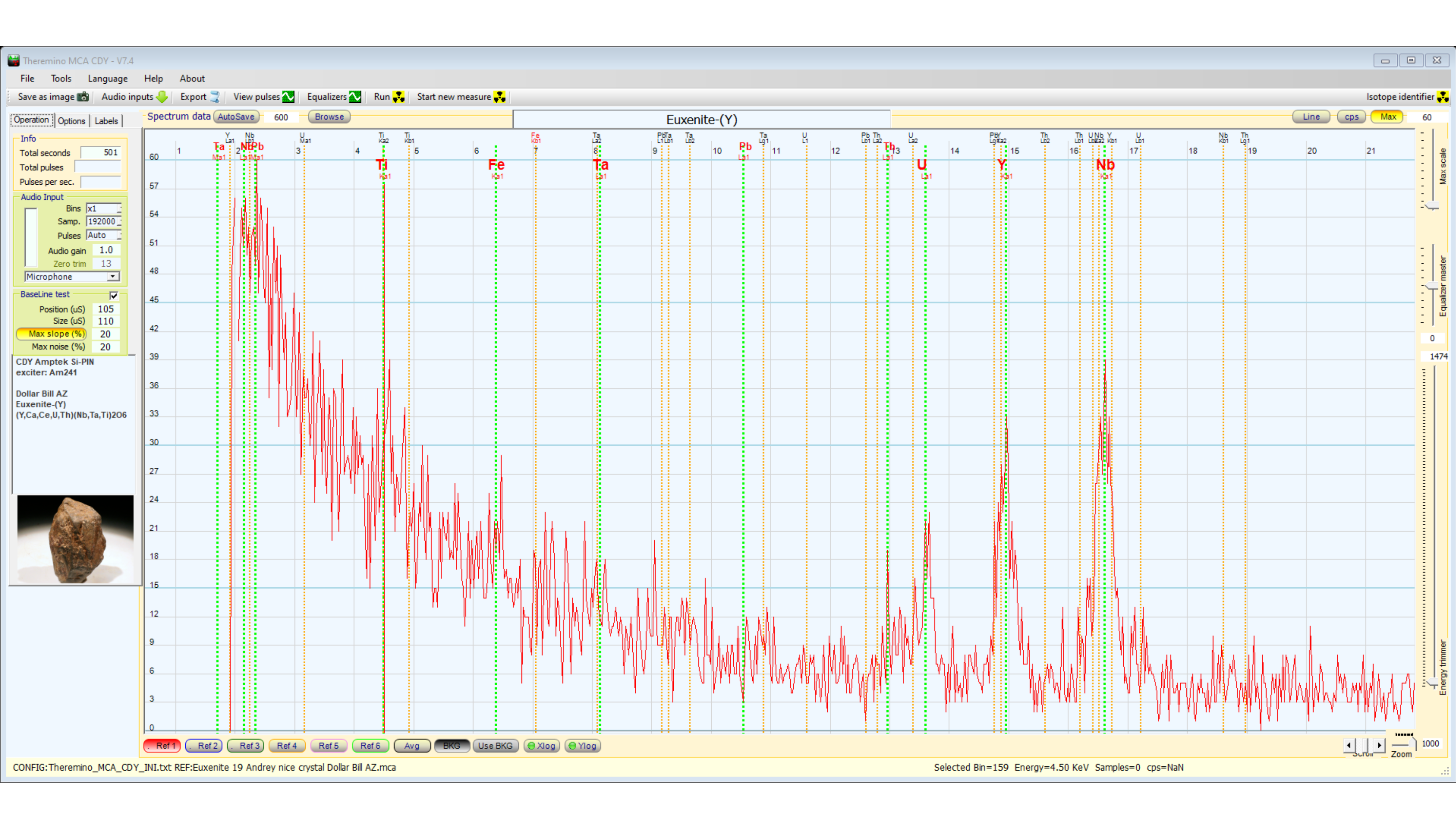
Charles Young did a quick XRF of the crystal above, showing that the Uranium peak is smaller than the Yttrium peak - characteristic signature of Euxenite-(Y).

Prospecting at the Dollar Bill Claim, Mescal, Arizona.
Another great video by Charles David Young.
The Gamma Dog makes it all possible - I can't imagine ever going back to any other detector for this application.

A quick overview of the Gamma Dog.