Sunday, July 12, 2020

Scintillation Gamma Spectroscopy: Shield

Since I was working with and using a lot of lead for my "Lead Pigs", I decided to prepare the shield of my Gamma Spectroscopy (GS) setup.
Shielding the GS detector from the environmental radiation is extremely important for low activity samples and detection of trace isotopes. Some weak peaks will be otherwise masked by the background radiation noise. The scintillating detector is a supper-sensitive device producing hundreds of pulses per second just from the background so the more Lead for shielding, the better! You cant really over do it with the shielding. There is a parameter called "halving thickness" for Pb and shielding can be easily 50lb or 150lb of Pb - based on what are the limitations - space, weight, cost, portability etc. 
Generally speaking, the weaker and smaller the sample is, the more shielding is needed. For example - energy calibration with 1uCi of Cs-137 requires no shielding, while looking for traces of Uranium or Thorium in a small mineral sample or soil could require hundreds of pounds of lead to bring the peaks out of the background. Traces of Co-60, producing high energy gamma in 1330 keV range could "hide" under the broad 1460 keV K-40 peak and at these energies a lot of lead is required.
Shielding for Spectroscopy, on the other hand is not that simple - "just pile up lots of lead" and you are done! Besides the environmental background, one should worry about what is taking place inside the shielded volume itself - samples emitting beta particles or strong gamma will cause secondary X-rays. This is also the case of low-energy X-Rays induced in the shield by the primary gamma rays as part of the Pb X-Ray fluorescence (XRF). 
Geometry and distance between sample and the detector crystal is also a factor in the efficiency.r Backscatter will produce additional peaks as well.
Additional shielding from different materials is needed to slow down the beta particles before they hit the lead in the main shielding and also to absorb / suppress the secondary x-rays - tin, bismuth, cadmium and copper are normally used.
My detector shield is constructed from 3 layers - outer shielding, which has a total thickness of 12.7 mm rolled lead sheet on a 4" form, a 22mm Lead cast main shield around the detector (made of two parts) and inner shield inserts made of thick copper foil and tin / pewter foil.
A final consideration is the mechanical constructions and geometry - the best ratio between shielding efficiency and amount of lead used (read: weight and cost) is achieved when the sample chamber is kept small and most lead is placed as close as possible around the detector.  As the radius increases, more lead is needed to achieve the same attenuation as when the lead is right around the sample volume and detector..

These are the tools I used for the casting process in addition to about 20+ kg of "soft" Lead ingots

The key component is this "5kg Casting Clay Graphite Crucible", purchased on eBay for $30.

The Lead ingots were melted down using a large propane "Weed torch". 
I constructed a very simple furnace out of concrete blocks. After all of the lead liquified, I scooped out the floating oxides and impurities with a steel spoon and turned off the flame. The crucible keeps the lead molten for at least 7-8 min with no flame going so there was a plenty of time to work with it. There is a little value in getting the molten lead very hot - it just oxidizes faster and one must wait longer for it to cool down.

To make the cavity /hole for the detector, I used an 8.4 oz can of Red Bull, tightly packed with fine sand and clay. I also added some cement just to harden a bit the contents - as the lead cools down it exerts uneven pressure on the walls of the can and it will wrinkle them if the walls are not supported. 
The can was inserted and centered into the molten lead and held in place until the Lead cooled and solidified. 
A word of caution (aside from the dangers of working with a large volume of molten metal) - nearly everything floats in molten lead so inserting the aluminum can all the way down to the bottom of the crucible, displacing the liquid lead,  centering it and holding it in place until the lead cools down - all this, while fighting with the can's buoyancy was a bit of a chore - thick casting gloves and a steel rod, inserted in the can as an improvised "handle" helped a lot. (it took 2 attempts until I got it right in terms of procedure and exact lead quantity). The bottom of the aluminum can had to be submerged,  initially, at an angle to allow the air to escaped from the concave cavity on the bottom of the can. This picture is from my first attempt - l kept this first cast and turned it into a "lead pig"/ sample holder-chamber.

 The cast shield, after emptying the can of sand and peeling it off the internal wall of the cast. A few taps with a small hammer punched the hole where the bottom of the can was - the lead is very thin in this area due to the concave bottom of the can and its sharp edge. It worked perfectly, leaving a nice round edge hole.
The thickness of the shield wall where the crystal of the detector is situated is more than 22mm and it tapers off  gradually in a "bullet shape" (after approx. 60mm height) to 6mm wall thickness at the very top.
As the lead cools down, it shrinks before solidifying completely, leaving an uneven void on the top of the cast. I used a propane torch to melt another 500g ingot and "top it off" filling all of the gaps and smoothing it out while the cast was fairly hot.
The inner wall will be covered with 3-layer "sandwich" of the inner shield insert - rolled tin pewter, 2" copper pipe and aluminum foil on the inside.

 All it took was just a few gentle taps for the cast to come out of the graphite crucible and the result is nearly perfect! The crucible's shape and material are optimal for an easy release of the cast.
The inside diameter is 55mm and overall height is 110mm (the dimensions of the crucible would have probably allowed me to add yet another 10mm of height)

 Here is the shield, in place on top of the sample holder.
The outside diameter of the shield matches perfectly the aluminum flange of my sample holder.

A strip of lead sheet 1/8" thickness, 6" wide and 60" long (~23 lbs of Lead) was rolled onto a 4" ID Schedule 40 PVC pipe form as a 12.7 mm  (1/2") thick Lead "sleeve" (4+ complete turns). Before rolling the lead, I also added 2 turns of copper foil over the PVC. The sleeve (pvc form + copper + lead) is held together with duct tape in a nice, tight, easy to handle package.

The entire sample holder is to be placed in a small lead castle made out of 1" thick lead bricks in a couple of layers - all around, overlapping a bit the bottom of the middle shield.
Start to finish it took about an hour to complete the cast.
There is a plenty of space between the shield and detector for the copper, aluminum and tin insert around the probe and lining also the inner lower volume, holding the samples.

I used the short cast from my first attempt and filled the bottom of the opening with about 1 lbs. of molten lead, creating an improvised lead "bowl" / chamber. This is my "large sample holder". 
I also cast a small 1 cm thick lid for when it is used as a stand-alone "Lead Pig" for temporary desktop storage of hot samples.


This is what the main shield looks when both pieces are put together. The bottom of the detector crystal sits just above the seam. 
With small samples, it is possible for the detector to be completely inserted, moving the crystal into the lower part. In this case, the top cap of the detector sits flush with the top of the shield and the detector is completely recessed.

I had to build a wooden box / cradle so I can keep everything together and transport the entire shield assembly. The shield is pretty heavy - over 35 kg of pure Lead. 1" Lead bricks create a base for the bottom portion of the main shield  (placed in a polyethylene foam spacer - later I replaced the polyethylene with wood). 
Also, visible is the copper foil lining the inside of the two parts of the main lead shield - self-adhesive copper tape was used to cover the inner walls. Inserts of much thicker rolled copper foil, as well as 2" copper pipe section are placed in the detector shield and the sample holder. All this is surrounded with tin-pewter sheets. The bottom of the sample holder is lined with a stack of 6 copper disks and 6 tin-pewter disks.

Some of the components of the modular lead shield.

Four Lead bricks are placed around the base of the sample holder . These bricks serve as a raiser for the outer sleeve.
There are 4 more bricks, laying flat, lining the bottom of the cradle, right underneath the sample holder.

The top of the outer shield sleeve sits flush with the top of the inner cast shield.

Using 4" PVC pipe, I made a "collar" shield for the top portion of the detector. 
8 Lead Ingots were placed on the inside of the form. I had to carefully select the 8 ingots from a pool of  about 20, until I found the combination that will fit in - still, some force and the use of a mallet was required to jam them up on the inside.

The two outer shield components.


The collar, placed around the top portion of the protruding detector. 
A lead cap with a hole for the coaxial cable is then placed on top.


The complete "Large sample" version of the shield in all of it's glory - almost 70 lbs of pure Lead.
This version is not as convenient to use as the tray sample holder and it requires partial disassembly / assembly to access the sample chamber but shielding is much better.
The shield is modular, easy to transport, it takes only a couple of minutes to put it together and can be used in different configurations.

The 1"+ thick lead cap on top of the shielding. The lead cap was spray-painted with "Plasti Dip" rubberized coating to protect from lead exposure as it is handled often. It was casted in the same manner as the main shield but using a steel rod to displace the lead and make the hole in the center so no drilling was needed.

The counts per second rate of the background without and with the shield, The unshielded probe is reading an average of around 110-130 cps. After inserting it in the shield, the rate drops down to less than 5 counts/ sec. This is a factor of over 10 times reduction in the natural background.

Histogram of the shielded detector background count rate - average 3.2cps is not bad at all!

As I mentioned before, you cant really over-do the shielding part when dealing with weak activity - the more lead, the better it is for reducing the radiation background noise and bringing out the weak peaks. 
I found my amount of shielding to be adequate for most of my experiments as I don't usually do "super-low" activity testing as in food, water or soil samples. 
The current setup IMHO is a good compromise between amount of lead shielding and weight / cost / portability. The whole shield can be dismantled and transported quite easily and it doesn't require a special, sturdy support table as it will be with 200-300 lbs lead castle. 

Sunday, June 7, 2020

DIY: Making a large "Lead Pig" container for Radioactive Minerals and Materials

  As my collection of Uranium and Thorium Minerals grew, I was in a need for properly shielded, large storage containers for my hottest specimens - I, certainly don't keep under my bed samples of torbernite, autunite or vials of Uranyl Nitrate but shielding is important factor in addition to distance.
Small "Lead Pigs" are readily available from a variety of sources, but these offer generally very limited space and are good enough to store small samples / vials with fairly low activity - mainly used in Nuclear Medicine. I normally use them to store vials with Uranium, Thorium or Radium compounds and very small mineral samples (unmounted, thumbnail size) or just as temporary desktop storage during experiments.
Any larger than an inch mineral specimens would not fit and often the thin lead walls simply would not provide sufficient gamma shielding - some rich minerals exhibit activity, well in the excess of 600K CPM. Furthermore, this is an extremely inefficient way (in terms of space and cost) to store large number of specimens even if they can fit in - not to mention that minerals are usually mounted and displayed in "Perky" boxes, which will never fit in these small containers. 
Large containers on the other hand get very costly to procure.

These small Nuclear Medicine "Lead Pigs" are fairly inexpensive and are available on eBay or from other online sources but the wall thickness can be as thin as 3/32" for the small ones although, most of them are with 1/8" lead wall and some of the better ones exceed 1" wall thickness. A nice feature of these containers is the secondary outer plastic shell container or epoxy paint which prevents you from handling bare, toxic lead metal. They are fairly light and easy to move around but the main issue I have, is the relatively small volume - they are really designed to contain small vials.

Thanks to eBay, I picked up a number of Lead sheets (99.9% pure Lead Metal) with size 12" x 12" x 1/8" and 8" x 15" x 1/8". Lead itself is not very expensive metal but shipping, due to it's density can run up the cost quite high - I've seen large, commercial lead-lined containers where the shipping cost is sometimes two times the cost of the actual container due to the enormous weight. Buying lead as sheets seems to be a good deal as often the shipping is just a flat rate regardless of the number of sheets, since the sellers use "USPS Flat Rate" boxes and can fold the lead sheets to fit.

Constructing the box is fairly easy - just like making a box out of cardboard in kindergarten - 4 cuts/slots, each approx. 3" long into the sheet on two opposing sides and 3" from each edge, then forming flaps by bending and folding the sheet of lead into a box. 
Using a sheet of 12" x 12" results in a box 6" x 6" x 3" and zero leftover. Pure lead is an extremely soft metal and easy to cut with a pair of  "aviation snips" - especially thickness of 1/8" or less. An added benefit of this size box, is that after folding it, two of the side walls will become actually 1/4" thick because of the folded flaps on the inside are doubling the wall thickness (later, I had to put 2 small inserts to fill the gaps because the internal flaps will get a bit shorter due to the bend radius)
To make the folds, I used two thick aluminum plates and a few clamps, sandwiching the lead sheet in the middle and using the edge of the aluminum plate for a nice, sharp bend, folding it by hand and tapping it with a rubber mallet.
The lid was made out of another 12" x 12" lead sheet with an overlapping lip of 3/4" and size of approx. 6" 1/4 x 6" 1/4. I just flipped the box over the stock sheet and traced the outline, then added the dimensions of the lip overlap. The folding process for the lid is almost identical to the one for the box but it was a bit more challenging, using bare (gloved, really)  hands, due to the narrow strip of thick material to fold.. Gentle taps with a rubber mallet along the sides did the job quite nicely. One can even do a Telescope-style box where the cover extends all the way down, essentially doubling  the side walls but I was going to use a larger hard shell and needed to be able to center the box inside.

Once the lid was cut and roughly formed, I folded the lid flaps (this time, on the outside) and using a hammer and series of gentle taps, I did the final fitting, so the lid closes nice and smooth. The Lead metal is so soft that hand forming it with a little bit of tool help (small rubber mallet and hammer) and one can achieve absolutely perfect and smooth fit. The total weight of this inner container when empty is about 12 Lb. and provides a volume of 108 cubic inches. 
I didn't use any sealant on the inside seams (corners / flaps) as I don't want it airtight and to trap any Radon gas generated by the Radium as a daughter product.

Such lead container can really benefit from a hard shell - the soft lead is fairly easy to accidentally deform and damage if the box is dropped, handled too roughly or just stacked.

I constructed a wooden box using 9" x 3"1/2 x 3/4" ("4 x 1 lumber") pine for the sides, 9" 3/4 x 9" 3/4 plywood for the lid and bottom and coated decking screws. 
The handles were made of strong Dacron rope and pieces of vinyl tubing for added comfort. The extra long handles afford more distance from your body when carrying the container. 

I made the outer wooden box slightly larger (8" x 8" on the inside) and lined the walls and bottom with the same 1/8" thickness lead sheet material. The top is covered with yet another, secondary lead lid - a removable 8" x 8" x 1/8" plate placed over the inner box lid (this plate can be setup as a portable shield, once the container is open).

Each of the side plates for the lining are sized 1/8" shorter the inside space and they lock each-other in place by being offset. The bottom square plate has dimensions with 1/4" shorter than the inside space and it is installed after the side plates, locking them into place so no additional fasteners are needed for the lining.
The holes for the rope handles were drilled thru the wood sides and the lead lining.

 
The height of the side plate lining is 1/8 shorter than the depth of the box, so when the top plate / cover is placed, it  sits flush with the to wooden box edge. The top lead plate (cover) is with the exact dimensions of the inside space and it rests on the edge of the side plates.

 I can add more plates or bricks of lead around the walls as more scraps become available from other projects or just fill the gap between the lining and the inner box with lead shot. Currently the total lead thickness of the inner box + lining varies between 1/4" (6.3mm) (top and bottom) up to 3/8" (9.5mm) (sides)
The whole thing is quite heavy in it's final configuration - 30 lb /13.6 kg. of lead.

My ultimate goal is to have at least 1/2" or more Lead metal all around. Lead sheets can even be nailed on the outside of the wooden box if need be - when it comes to gamma ray shielding there is nothing wrong with over-doing it (except for the weight). 
1/2" Lead provides over 50% attenuation of Gamma Rays (also known as "halving-thickness") at up to 2 MeV (this is the equivalent of 1" steel or 7.2" water shielding). There is a point of a diminishing returns though - the amount of lead and the weight would not justify the amount of attenuation for low amounts of activity - you'll need for an example 3 cm of Lead (~1"  3/16) to attenuate the intensity to 1/8th of the original intensity. 
I also added HDPE (High-Density Polyethylene) plates (polyethylene is a very hydrogen-carbon rich plastic, which works well as a neutron shield / moderator, not that is needed here) to fill the gap between the inner lead container and the outer lead sheets, lining the inside walls of the wooden box. This acts as "padding" and keeps the inner box centered so the lid can be easily removed. 
Natural Uranium contains 0.7% of  235U, known for it's spontaneous but neutron yield is absolutely not a concern. Solid blocks of paraffin (candle wax) would work OK for those planning to store strong neutron sources (252Cf anyone? 😀) 
This HDPE filler between the inner and outer box can also be substituted with small lead bricks or lead shot (from a local hunting supplies store) , if one is willing to deal with the extra weight. 
Future plans include to line the inside of the inner container with a "sandwich" liner of aluminum and copper foil - this will slow down the beta particles before they reach the lead shield and are abruptly stopped, thus reducing the generation of secondary low-energy X-Rays (the Bremsstrahlung effect caused by the rapid deceleration of a beta particle).
These X-rays can not make it thru the lead but can be an exposure factor when one is digging thru the contents. 

The Lead Box and my Infab Revolution Maxi-Flex X-Ray Lead Gloves (0.50mm Pb equivalent) for lengthy handling of extra hot samples or just digging thru the contents of the lead containers. 

I intentionally left the lead surface as bare metal and didn't paint it or cover it with duct tape, self-adhesive vinyl or rubber spray-on coating (all, good options btw.) for two reasons - one day I might need to re-use it for a different project (and don't want to deal with sticky residue) and also the bare lead metal lid (as weird as it might sound) is a good reminder for me: *GLOVES ON* when handling the contents of box (and honestly I do like the bare metal look).
All mineral samples inside, are organized by activity - the ones with highest activity are positioned towards the center of the volume and the lower activity rocks are placed around the perimeter as a natural shield.
I also installed a plywood cover with two small hinges to complete the outer box - all from Home Depot.
The wood surface was later covered with clear polyurethane varnish after applying the graphics. 

I built two of these "lead pig" containers.

I thought, at this point the containers were worthy of some stenciled graphics! 😀 
This way, it is easier to identify them as well.
After painting on the graphics, I applied 3 coats of clear polyurethane varnish. 

Yet another option is a Lead lined Ammunition steel can - in this case I used a .50 BMG Ammo Can which provides an ample space for large specimens - volume is approx. 11" x 6.5" x 5.5"
 The main drawback is the container's shape - "tall and narrow" so things have to be piled on top of each-other - not as optimal as the shallow boxes I made previously. In addition, a single handle is not the most convenient way to transport it if the lead lining is more than 1/4" - it gets awfully heavy to carry with one hand. 
On the positive side - lining with lead is very easy and straightforward - 1 x U-shaped piece of lead sheet for the large side walls and the bottom combined, 2 pieces of lead sheet for the front and back walls and yet one more for the lid. The front and back lining is the exact size of the walls and it is placed first. The U-shaped large piece is placed second and locks the other two pieces of lining in place.
The steel container is also very sturdy and air-tight due to the rubber gasket.

Stencil and Airbrush and the final look is pretty cool!

A probably unnecessary safety warning: use gloves when working with Lead, don't eat / drink while doing while dealing with lead metal and wash hands very well afterwards. Methods of cutting (like a saw or Dremel tool) which create lead dust are bad idea and will require respirator and cleanup.

Actual Lead Pig 😀

Saturday, April 18, 2020

How Diffusion Cloud Chamber Works?

Theory of operation of the Cloud Chamber is fairly simple yet brilliant.
The Diffusion Cloud Chamber is basically a sealed volume, filled with Alcohol Vapors.
Conditions are created for a steep vertical temperature gradient inside the volume.
Alcohol is evaporated from a reservoir near the top of the volume where the temperature is higher and vapors fall down as they cool, towards a very cold plate at the bottom.
Just above the cold plate, the alcohol vapors reach a supersaturated state due to the deep cooling (colder than -26℃). 
In this state, the air above the cold plate is so saturated with alcohol vapors and they are cooled beyond the threshold of condensation (dew point) so the vapors only need a trigger - a "seed" around which to start the process of condensing into small liquid droplets, just like a normal fog.
The ionization trail of a charged particle provides these condensation "seeds".

(c) 2020 Andrey Stoev

(please note that the graphical representations of the elements above are not to scale with each-other in order to improve the clarity of the diagram)

When a charged particle enters the volume (or it is created inside) and passes thru the Cloud Chamber's Active Zone, it leaves an ionization trail. 
Gas atoms of oxygen and nitrogen from the air become Ions in the path of the energetic particle as the particle collides with the gas atoms and deposits some of its energy while knocking off electrons.
Once the atoms are stripped from even a single electron, the charge balance is no longer present - the atom becomes positively charged due to the positive charge of its nucleus.
Since the Alcohol and Water molecules are slightly polar, the molecules are then attracted to these ions. The ions serve as "seeds" / condensation centers and droplets of fine mist form around these condensation centers, tracing the path of the particle.

The condensation trails appear only in the active zone where conditions are right (alcohol vapors are supersaturated) and are white in color just like the normal water-based fog.
Black background and intense tangential lighting helps to improve the contrast, bringing them out and making them more visible to the observer.

Improved observation conditions are achieved by deeper cooling which extends the thickness of the Active Zone layer by creating a steeper temperature gradient.

Another feature (optional) which greatly improves the performance of the Cloud Chamber is the Ion Scrubber. "Ion Scrubber" is the scientific term for High-Voltage Electric Field applied to the chamber's volume. Typically, between the cold plate (-) and an electrode (+) suspended above the cold plate. 
CERN recommends about 100V/cm field potential.
The electrostatic field improves the performance of the Cloud Chamber in the following ways:
- clears the volume from airborne dust particles and contaminants at startup - this removes unwanted condensation centers
- deflects the con-trails in the Active Zone for a better observation
- "resets" the chamber by quickly removing (scrubbing) the ions so condensation trails don't linger for too long and new ones can be observed
- prevents ions from creating an alcohol "rain" over the active zone.
- improves sensitivity of the Cloud Chamber and increases the definition of the con-trails, making them crisp and well defined by quickly stripping off the "fuzzy" outer part of the con-trail.

It is very important that the air inside of the chamber is perfectly still as the fine vapor trails are very "fragile" and they will quickly disperse in the presence of air movement / turbulence. Any air leaks from outside will also bring in warmer air which will interfere with the operation of the Active Zone - a good, air-tight seal of the volume should always be maintained during operation!

Large Cloud Chambers usually have a special port to bring in radioactive samples or inject radioactive gas (Radon) without much air disturbance. Such specimens can be introduced also by gently opening the volume (lifting the cover) but it will take a few seconds for the conditions inside to normalize and the con-trails to reappear.

Trivia (credit: Wikipedia)
The invention of the cloud was Charles Thomson Rees Wilson. This was his signature accomplishment, earning him the Nobel Prize for Physics in 1927.  The Cavendish laboratory praised him for the creation of "a novel and striking method of investigating the properties of ionized gases". The cloud chamber allowed huge experimental leaps forward in the study of subatomic particles and the field of particle physics, generally. Some have credited Wilson with making the study of particles possible at all.
Cloud chambers played a prominent role in experimental particle physics from the 1920s to the 1950s, until the advent of the bubble chamber. In particular, the discoveries of the positron in 1932 and the muon in 1936, both by Carl Anderson (awarded a Nobel Prize in Physics in 1936), used cloud chambers. Discovery of the kaon by George Rochester and Clifford Charles Butler in 1947, also was made using a cloud chamber as the detector. In each case, cosmic rays were the source of ionizing radiation.
The diffusion cloud chamber was developed in 1936 by Alexander Langsdorf.

Sunday, April 12, 2020

Diffusion Cloud Chamber (Conclusion)

The Diffusion Cloud Chamber in operation!
 
The complete Cloud Chamber setup, ready for power up!

The clips bellows are from the very first test of the completed Cloud Chamber.
Best viewed in a full-screen mode!

The Cloud Chamber is capable of displaying only charged particles such as α-particles (Helium nuclei), β- particles (electron), β+ particles (positron), μ (muon), Cosmic Rays / proton clusters, etc..
It will not display neutrons, neutrinos and any other sub-atomic particles without a charge.
When I say "display", you don't see and you cannot see the actual particle but rather the ionized path and the resulting  condensation trails left behind a charged particle going thru the volume. 

I injected the Cloud Chamber with "Thoron" which is a short-lived isotop of Radon - 220Rn has a half-life of only 55.6 sec and it is an α-emitter (6405 keV). It is a daughter product of 224Ra, which, on the other hand is further down the decay chain of Thorium (232Th).
My son's reaction to this α-particle fireworks display was pretty rewarding!

Here is another example of Radon-220 ("Thoron") in the Cloud Chamber. To obtain the "Thoron", I placed a Thorium Gas Mantle (Thorium Dioxide - 232ThO2) inside a large syringe and capped it for a couple of days - no point of waiting more than that as it is a very short-lived isotop (55.6 sec) and it will decay quickly after it is produced by Radium-224 (one of the Thorium series decay daughter products) so no substantial accumulation will occur. (In a couple of days, inside the syringe, near an equilibrium state will take place - the concentration of 220Rn will become stable as new 220Rn will be generated to replace the one which is decaying at that moment.)
I lifted the edge of cover and gently injected the air and Radon mixture from the syringe into the Cloud Chamber.
Similar experiment can be done with another Rn isotop - 222Rn generated by Radium Watch hands but then it is worth waiting at least 3-4 days longer for more Radon-222 to accumulate inside the syringe - 222Rn has a half-life of 3.82 days.
As a side experiment, after removing the Thorium Mantle from the syringe and expelling the gas contents, the "empty" syringe was still producing an activity of around 150 CPM on the outside due to β- decay of other solid daughter products deposited after the Radon decay - namely 212Pb and 212Bi.
 This β- activity, as expected died out quickly, over the next few hours and normalized to background levels as the decay chain reached the stable 208Pb. 

The clip shows some high energy β- particles and some low energy β- are also visible. Around 0:08 there is nice Y-trace, showing an interaction with an atom by a high-energy β-. One leg of the Y is sort of zigzagging probably from the knocked off low-energy electron, the other leg of the Y is straighter, created by the original particle. There is also a nicely deflected low-energy β- at around 0:07.

An α-particle, then a low-energy β- particle and at the very end a high-energy β- or a muon (μ).

Some really nice particle interactions!

This is the equivalent of a "Sub-Atomic Particles Disco-Club". On the left is a Natural Uranium doped glass marble, emitting mainly alpha particles and some beta by daughter products. In the center is a pellet of 241Am (a very strong α emitter) and on the right is a vial filled with Tritium (3H) emitting very-low-energy β-.
This video is from an early test before the Light bars were fully constructed.

A tiny piece of Uranium Ore (Uraninite infused matrix) attached to a Lego square. This piece produces only around 1000 CPM @ 1 cm from my GMC-600+ Geiger Counter. By the time this clip was filmed, the mineral was already covered with liquid alcohol condensate so not that many Alphas are able to escape but plenty of Betas can be seen, emitted by Uranium decay daughter products. The Cold Plate has been running at a steady -35.5℃ for over an hour -  the room temperature is +23.5℃.

This clip shows the Ion Scrubber in action and the difference it makes during operation! On the left side there is a tiny piece of Uraninite (UO2) attached to a Lego square. There is a distinctive loud "click" in the audio from the switch when the High Voltage (HV) is turned OFF or ON. The first 10 sec. of the video is with HV turned ON, then 10 sec. of HV turned OFF and then again 10 sec. of HV turned ON. One can note that when HV is OFF, the tracks become "fuzzy" and less defined. Currently, the Ion Scrubber operates at 4.3 kV but I am planing to add a circuit for voltage adjustment.
The background clicking is from a nearby Geiger Counter.

A word of Caution: Aside from Nuclear / Radiation Safety (dealing with radioactive materials is not something, I will encourage without the proper understanding and training!!!) one should be very careful not to contaminate the volume of the Cloud Chamber - this can affect later observations of the background / cosmic radiation!

I must say, this was a real fun project to work on and a true kitchen table / garage project! My son and I had great time designing and working on the Cloud Chamber and the results absolutely exceeded my expectations. It is a nice portable setup and I have the feeling my son will be bringing it to school more than once.
Unfortunately, the Science Fair, we built the Cloud Chamber for was postponed due to the COVID-19 Pandemic but this will give him time to prepare all of the supporting materials and diagrams.
On the bright side, besides being a Cloud Chamber, this instrument is a good platform to demonstrate, study and experiment with multi-stage Thermo-Electric Coolers.
The High-Voltage Power supply and adjustable electric field strength is also useful for experimentation with electric fields.
The Liquid Cooling Plant is quite useful too for various physics, chemistry or electronics experimentation.
Just as with a Telescope - now I wish the Cloud Chamber was a bit bigger :-)
Next project on the table - DIY Gamma-Spectroscopy!


Diffusion Cloud Chamber (Part 4)

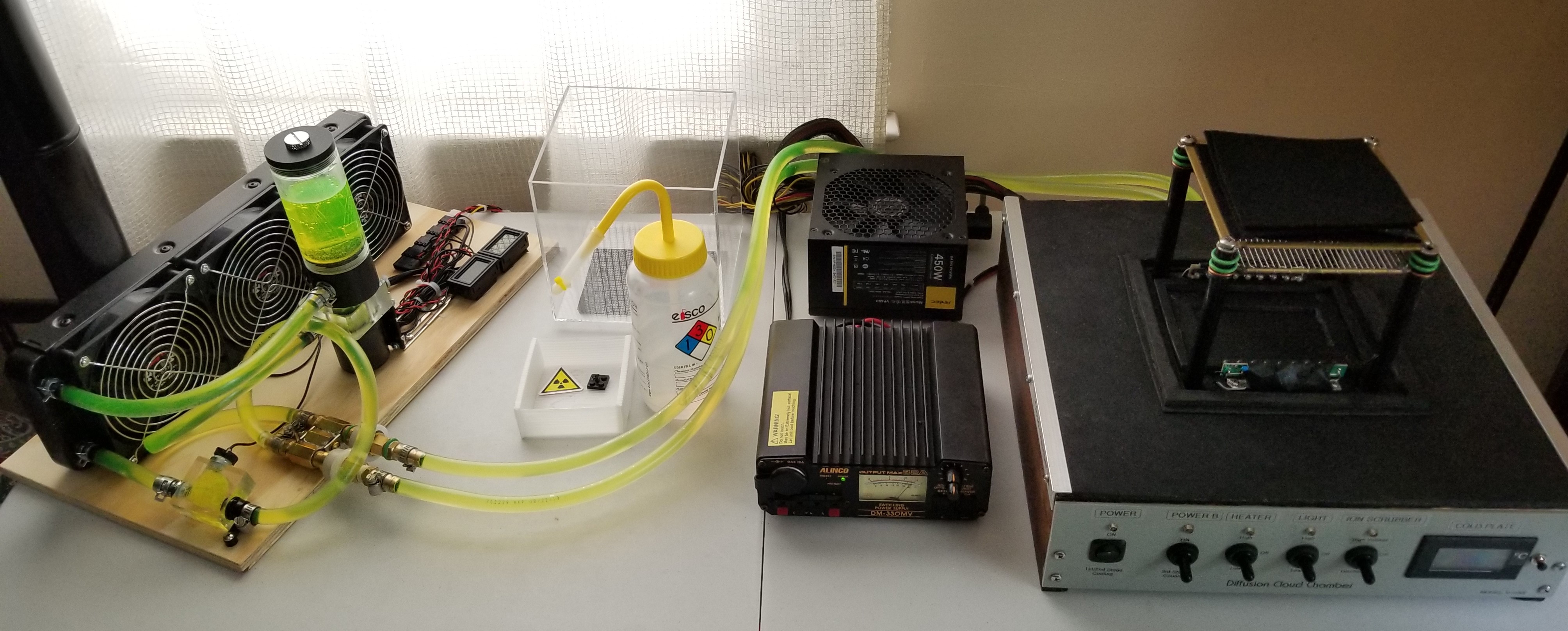
The Liquid Cooling Plant (LCP) was constructed on the same 1/2" plywood material (10" x 17") as the Cloud Chamber's top surface. 
One of the design goals for this project was a modular system approach. Usually, desktop space is very limited during a Science Fair at my son's school and we wanted to preserve it for supporting materials. By having a physically separate Liquid Cooling Plant, this cooling module can be placed on the floor or somewhere else, out of the way, keeping the focus at Cloud Chamber's Main Unit. The Static Head Lift of the coolant pump is listed as 5 meters which is more than enough if placed on the floor!
Another benefit of a stand-alone LCP is that this module can be used for other experiments requiring liquid cooling - all is needed is another pair of male Quick Connect/Disconnect adapters. For example, it can be used in our Chemistry Lab for distillation procedures, without the need for constantly running water.

The Liquid Cooling Plant for Stage 4 cooling is using a large, densely finned Heat-Exchanger / Radiator with 18 channels (normally used for Laser or PC water cooling), 3 large fans, a centrifugal water pump /w coolant tank, visual flow meter, two digital thermometers and Quick Connect/Disconnect ports.
All liquid coolant interconnects are done with 3/8" ID 1/2" OD vinyl tubing. 
I had to replace the G1/4 to 5/16" barb fittings for G1/4" to 3/8" fittings on the water pump and flow meter to accommodate the larger diameter tubing. The tubing management is not fantastic - the 1/2" OD tubing and the small footprint of the base made it a bit difficult to route all tubing in a neat manner while avoiding small radius bends which can "pinch" the tubing.

The fans are configured to suck the air thru the radiator and can be used at the same time to blow air at and cool down the high current Stage 3 (18A) Power supply when placed in front of the fans.
A flow-meter with a spinning propeller gives a visual feedback about the speed of the coolant flow. This housing is also used to accommodate the inlet temperature sensor.

The Centrifugal Water Pump is 12V / 19W unit with an alleged specified flow of 800L/h and Static Head Lift of 5 meters. The pump is gravity-fed from a coolant tank just above it. It is configured to pump water into the cooling water blocks and the return line goes thru the flow meter, into the heat exchanger and the output of the radiator is fed back into the coolant tank.

Two digital thermometers display the output and returned water temperatures. The output water temperature is measured at the water tank just before the pump inlet. The sensor for the returned water temperature is located at the flow-meter housing.
The female Quick Connect/Disconnect ports were a bit tricky to mount. We had to fabricate special aluminum L-brackets to mount the assembly firmly in place. I used 3 x 1/4" Female-Female brass couplers soldered together side-by-side in order to mount the Inlet/Output ports on one side and the adapters MIP to 3/8" barb to the other. The whole QC assembly was mounted by threading a long brass screw thru the middle 1/4 adapter (acting as a spacer) and the two supporting L-brackets already mounted on the plywood.
Using Quick Connect ports makes it extremely easy and fast to put the whole setup together and to drain the coolant when done.

The heat-exchanger / radiator  (393 mm  x 120 mm x 32 mm) is attached with L-shape aluminum angle bracket to the plywood base. It has 18 internal finned channels side-to-side.
The entire cooling system, including tubing and water cooling blocks takes about 600 mL of coolant and it is fully sealed.

The water lines 3/8" ID 1/2" OD and male Quick Connect/Disconnect adapters on the Cloud Chamber side.

Due to the fast coolant flow and overall efficiency, the temperature differential at the heat-exchanger is not large but the system cools the water efficiently, maintaining a constant temperature of about 3-4°C above the ambient air temperature.
The Digital Thermometers are powered from the +5V line on the main wire harness. The 3 cooling fans and the water pump are powered with the +12V line.

It takes about 10 minutes for the temperature to drop down to the nominal -36°C due to the large thermal mass of the copper Cold Plate - thickness of the plate is 6.3mm. Again, due to the same large mass the temperature is very stable and rises slowly when power is turned off.  First particle tracks appear when the cold plate reaches about -28°C. Due to the plate thickness, I am probably loosing a couple of degrees at the minimum temperature end but on the other hand, temperature is very evenly distributed across the active zone surface.

Using high concentration of Isopropyl Alcohol (Isopropanol) is absolutely critical for proper operation. The higher the concentration is, the better the Cloud Chamber will work. 
We use 99.9% Lab Grade pure Isopropyl Alcohol and results are excellent. In theory, everything above 91% should work but using >95% is highly recommended! 
Isopropyl Alcohol has the lowest Ionization Energy (IE) level - 10.10 eV of the 3 popular types of alcohol, and it is the best choice! Ethanol (IE ~10.48 eV) or Methanol (!Poison!) with IE of 10.85 eV will also work.
A couple of Squeeze Alcohol Wash-Bottles are a very handy accessory - one bottle, filled with alcohol to saturate the felt reservoir of the Alcohol Evaporator Unit when priming the Cloud Chamber for startup and an empty bottle to periodically collect the alcohol condensate from the Cold Plate and recycle it.
A "must-have" accessory is a "Lead Pig" (Lead Lined Container) to store radioactive samples - Americium-241 pellet from a Smoke Detector, Thorium Gas Mantles, Thoriated Welding Rods, Uranium Glass, Tritium Vials, Ores, Minerals etc., as well as pair of tweezers to handle the samples. I have a few different lead container sizes for storing radioactive samples. Plastic covered Lead Pigs are the best choice for small, "Cloud Chamber ready" samples - due to the lead's toxicity one should avoid handling bare lead metal.
For larger specimens, I prepared lead lined boxes.

This is complete Main Unit of the Diffusion Cloud Chamber!

Building the Cloud Chamber took us about a week of build time, but it was actually stretched over a month due to delays with some parts and issues with the eBay shipments.

Diffusion Cloud Chamber (Part 3)

All cable interconnects for this project were salvaged from old PC power supplies. The only exceptions are the Teflon insulated corona-free HV cable (rated at 15kV) and all top-side wires (for heater and light bars) which are silver-plated Teflon insulated stranded wire. All rocker switches are rated for 20A but the only critical circuit in terms of max current is the Power B switch for the 3rd TEC Stage where the current is 18A.

This is the underside of the completed Cloud Chamber. 
Removing residual heat left after the liquid cooling stage helps a bit by lowering the temperature by another 2-3°C. To accomplish this, a system of fans was designed - two small fans blow air horizontally across the fins of the heatsink, while another exhaust fan picks up the hot air on the other side of the heatsink and blows it out in the open thru the back of the enclosure. This system works for the tight space we had to work with. The screws keeping together the Cooling Unit "sandwich" are used to support the brackets for the exhaust fan and the thin plastic air guides using a set of stand-offs.

The intake pair of fans and the blue exhaust fan. Sheets of thin transparent plastic form air channels to contain and direct the stream of air into the fins of the heatsink.
An aluminum L-bracket secures the two stainless steel T- splitter for the coolant - the bottom one on the picture is the inlet for the cold water and the top one is the warm water outlet. The splitters also act as adapters converting the 3/8" ID water supply tubing to 2 x 1/4" ID silicone tubing connected to the copper water cooling blocks.

The front panel's Industrial Digital Thermocouple Thermometer (Lascar DTM-995B) is on the right-hand side. DTM-995B supports T, J and K-type thermocouples, it has a switchable backlighting, °C/°F display units and switchable Current/Min/Max display (a little button, installed next to the display, not seen in the pictures, scrolls through the 3 readings). I installed a Cryogenic-optimized Type T thermocouple and the thermometer was calibrated for this probe before the installation at the Cooling Unit. K-type thermocouple which is more common can also be used but it is not as accurate at low temperatures. There are two adjustments on the back of the thermometer for calibration - Offset to set the 0°C value and Calibration for 100°C

Due to the close proximity between the thermocouple probe cables / thermometer and the HV lines leading to the Discharge switch, additional insulation (Neoprene foam sheet) was added and zip-tied to the HV cables. Any arcing there can destroy the digital thermometer or the power supply.
I took apart an identical switch to the one used for the HV/Discharge circuit and made sure that the distance between the contacts is at least 2 mm in the opposite throw of "Discharge" when the switch is in HV ON position - this should be enough to prevent HV leakage / arcing thru the Discharge circuit inside the switch as Air breakdown Voltage is generally 3kV/mm.
I was toying with the idea of using a HV vacuum relay instead of the switch but it was going to be just over-engineering on my part for only 4kV.

Thin, transparent plastic sheets, salvaged from plastic packaging are used to create a "scoop" for the heatsink exhaust hot air, just above the exhaust fan. This guide directs the hot air coming out of the heatsink fins directly into the blades of the fan. The exhaust scoop is visible on the right, partially covering the 3 switches. The sheet separating the air intake and the air exhaust can be seen on the left/center of the picture and it is secured by the screws on the heatsink.

In this picture, on the right side, one can see the two power resistors (50 Ohm (2 x 100 Ohm /3W in parallel) and switch used to control the power levels to the heater. Heater power is switchable between 1W on LOW (running)  and 1.4W on HIGH (start-up).
The 3 terminal strips are used to distribute different PS voltages to various circuits of the Cloud Chamber - this makes it really easy to change the power configuration of the TEC modules.

Proper tangential lighting above the Active Zone is absolutely essential for good observation of the vapor trails left behind the charged particles. We used 2 opposing light elements - each light bar contains 9 evenly-spaced Super-Bright White LEDs. The LEDs are mounted very low, just above the Active Zone, illuminating the supersaturated alcohol vapors at a steep angle. Standard 5mm LEDs with a built-in lens work best providing sharp bright light beams compared to large diffuse light LEDs.
The 18 LEDs are electrically divided into 6 groups and each group of 3 LEDs in parallel has its own 150 Ohm current limiting resistor. There is a simple Brightness control facilitated by a potentiometer and DPDT light switch with OFF, HIGH and LOW (adjustable) beam settings. LOW brightness includes a 1 kOhm trimmer-potentiometer in the circuit, allowing for a variable brightness level. This can help when doing long exposure still photography or videography of the Active Zone of the Cloud Chamber.
Two PCB strips with width of 1cm are used to form each Light bar. The strips are attached to each other at 90 deg using heavy gauge solid bus wire. The PCB design is fairly simple and can be etched easily at home or the copper can be mechanically removed with a Dremel tool to form the pads and traces.
Visible on the picture is the closed-cell foam "Vapor Fence" intended to contain the supersaturated alcohol vapors above the cold plate so they don't spill over the entire surface of the volume.
Since the vapor trails are whitish, everything inside the Cloud Chamber should be colored black for maximum contrast and visibility of the white trails.
The Active Zone is covered with Black Self-Adhesive Aluminum foil - this type of foil tape is ideal for the purpose as it has a wide temperature range adhesive, it has alcohol-resistant paint and it is heat conductive. This kind of tape is normally used in Broadcast studios by the Lighting Technicians to modify / mask studio spot lights and in comes in 2" width.
Also visible here is the outer Neoprene foam seal for the chamber's cover.
The air inside the chamber must be perfectly still so the vapor trails are not disturbed by air turbulence when formed. This seal prevents any air from coming in or out when the volume cover is in place, eliminating any draft and possible air turbulence.
All seams on the bottom and around the Active Zone are sealed with Black RTV Silicone sealant to prevent alcohol from seeping thru and infiltrating into the Cooling Unit.

This is the finished top side of the Cloud Chamber setup without the volume cover.
The top surface of the chamber's enclosure is covered with a fairly thin (~ 2 mm) black rubber sheet (We picked up this in the flooring section of Home Depot). The rubber sheet was glued using non-foaming Gorilla Glue to the top of the plywood. Gluing this rubber sheet was a bit tricky though - I had to make a jig to clamp and provide even downward pressure on the entire surface while the glue was curing to avoid any wrinkles or air pockets but the result turned out to be excellent.
Aluminum L-shaped profiles are used as a trim for the side edges of the enclosure.
The rubber surface around the chamber's volume provides a nice, durable, non-slippery, alcohol-resistant work area which can be used for additional experimental equipment, specimens, photographic equipment, etc.

The Heater element of the Alcohol Evaporator Unit. The Cloud Chamber relies on a steep temperature differential / gradient between the top part and bottom part of the chamber's volume. Raising the temperature of the top side helps with the alcohol evaporation. We constructed the Heater element from 6 x 68 Ohm (0.25W) resistors organized in two parallel strings - each string has 3 evenly spaced resistors in series. The total resistance of the heater is approximately 100 ohms, dissipating 1.44W at High setting. At Low setting, the heater runs thru an additional 50 Ohm resistance and the heater element dissipates 0.64W.
The heater is powered with 12V from the main power supply. The resistor strings are connected to Teflon insulated wires and placed inside heat-shrink tubing, . A small pair of barrel connectors (M/F) is used for the electrical connection, making the heater replaceable / interchangeable in case we decide to experiment with different heaters / power levels.
The power supply line for the Heater comes thru the top surface, goes into one of the Delrin rods thru a hole on the side and exits from the top opening, terminated by the heater jack.

The completed Alcohol Evaporator Unit. The Heater element is inserted between 4 sheets of black felt squares. The felt squares serve as "alcohol reservoir" and are thoroughly soaked (but not dripping!!!) with Isopropyl Alcohol before the Cloud Chamber is closed and started. Felt material is ideal for releasing the alcohol vapors as it provides a very large surface area and even evaporation. Different number of felt sheets can be used for different run times / amount of alcohol. Heat is absorbed by the top and bottom sheets and alcohol vapors seep thru the mesh supporting them above the Active Zone of the Cloud Chamber. With 2 felt squares the Cloud Chamber can run for about 1.5 hours before it requires removal of the alcohol condensate from the bottom plate. This can be done with a Squeeze-bottle, syringe or just soaked with one of the felt squares and then recycled.

The High-Voltage Positive Supply line comes thru the top surface and connects to the Ion Scrubber mesh on top. The wire is inserted in a black heat-shrink tubing and spliced to a thinner and more flexible Teflon insulated wire, which allows for the metal frame holding the mesh to be adjusted up or down as needed.
While the Cloud Chamber will operate without an Ion Scrubber (IOS), the IOS greatly improves the performance of the Cloud Chamber and IMHO it is a "must-have" feature. 
The electric field cleans the air from dust contaminants when the Chamber is first started and vastly improves the visibility and the definition of the vapor trails by quickly removing (scrubbing) the ions. With IOS turned off, tracks are much thicker, linger for a longer time, less defined and much lower in number. When IOS is turned ON the effect is rather dramatic - the number of visible tracks jumps many times, tracks are very crisp and well defined and the chamber quickly resets itself, clearing old trails.
Total of 4 cables come from the bottom compartment to the top surface - 2 x for the two Light Elements, the High-Voltage IOS supply line and the Heater lines. The rubber top surface provides a very nice and tight seal around each cable as it tries to self-close.

The transparent acrylic Cloud Chamber cover. It is a 6" x 6" x 6" inches (inside) hollow, 5-sided cube and provides enough vertical height for a good temperature gradient and excellent viewing angles. We picked up the acrylic cover on eBay, sold as Trophy / Memorabilia cover and it works for the purpose as a temporary solution during testing but it will be replaced with a custom-made glass cover.
This cover contains and seals the volume of the chamber and it is best if it is made out of glass - we are planning on using 3/16" glass when the cover is replaced (just the standard "fish-tank" type construction and silicone adhesive). Acrylic plastic doesn't react well to saturated alcohol vapors and low temperature - eventually it becomes brittle, cracks and flakes.
 I designed a special "Neoprene" foam seal for the bottom edge of the volume cover. This seal is air-tight and completely seals off the volume of the Chamber when the cover is inserted. It is made of 2 different thicknesses Closed-Cell Rubber Foam material - the thin, bottom layer seals the under-edge of the cover - it has an inside lip on which the cover "steps on", while the thicker outside foam rim seals the cover on the outside wall. The seal is glued with black RTV Silicone to the top surface and provides also mechanical stability of the cover as it is a tight-fit and locks-in the cover in place.

Update: Finally, I built a proper volume cover to replace the acrylic one . It is made of 3/16" thickness glass with an inside dimensions of 6" x 6" x 6". The glass sides are glued together with clear RTV silicone sealant (just as if you are building a box or a fish tank)  and then the edges were reinforced and protected by gluing over each of the edges an aluminum angle (L-profile) 1/2" x 1/2" x 1/16".
The top edge trim was made of the same material in sections of 6" with 1/2" cutout on one of the sides to cover each corner's top side.
I built the cover in 3 steps - first is to glue the glass, after the silicone completely cured, I removed all the excess from the seams (inside and outside) and then glued with the same sealant, the corner aluminum L-trim. Working with silicone gets very messy and you have only a limited time before it starts setting so doing it in 3 steps affords more control over the build process (but the cleanup stage can be time-consuming and I recommend using masking tape to minimize cleanup).
The bottom 1/2" glass of the side edges was left without the protective trim in order to ensure a tight side seal when the cover is inserted into the custom gasket.
The bottom edges were trued by polishing the cube edge over a very flat, machined surface with sandpaper until the edges became smooth and straight on the bottom for a really good seal.