
My DIY Gamma Spectroscopy setup is finally completed!
A Gamma Spectroscopy system is comprised of 6 major components:

1. Spectroscopy-Grade Scintillation Detector - this is the single most important component and the "heart" of the system.

The detector is an RF and magnetically shielded (with Mu-Metal) and light-tight assembly of a scintillation crystal or scintillation plastic (for example NaI(Tl) - Thallium doped Sodium Iodide, CsI(Tl), CeBr3, LaBr3, Bicron plastic, etc). The crystal itself is surrounded with MgO reflector, except for one of the sides interfacing the Photomultiplier Tube and encapsulated in an air-tight aluminum canister with a glass window. NaI is an extremely hygroscopic compound, and it must be perfectly sealed to prevent moisture from destroying the crystal.
The canister's window is is coupled via an optical interface (optical grease) with a Photomultiplier Tube (PMT) and a Dynode Voltage Divider for the PMT bias is usually mounted on the PMT's socket.
The low-energy light photons produced by NaI(Tl) crystal as a result from high energy gamma photon excitations are in 320-550 nm wavelength range with a maximum emission at 415 nm.
In my setup, I use a Scionix Holland 38B57/1.5M-E1 detector with NaI(Tl) crystal 1.5" x 2.25", Hamamatsu R980 10-stage PMT and a dynode voltage divider, I custom built with 2M for R or total impedance of 24M.


 I removed all of the old components and had to figure out way how to apply the new divider circuit using the old PCB, traces and pads.
 The board was cleaned from solder and old flux before soldering the new voltage divider components - all of them are SMDs. The pin numbering on this picture is wrong! This was a temp numbering as if using 14pin socket - this PMT has 12 pins - 10 stage dynodes, Anode and Cathode.

 The PMT's dynode voltage divider - a pretty standard circuit with the exceptions of the values in my case R is 2M and R1 is 2R or 4M.


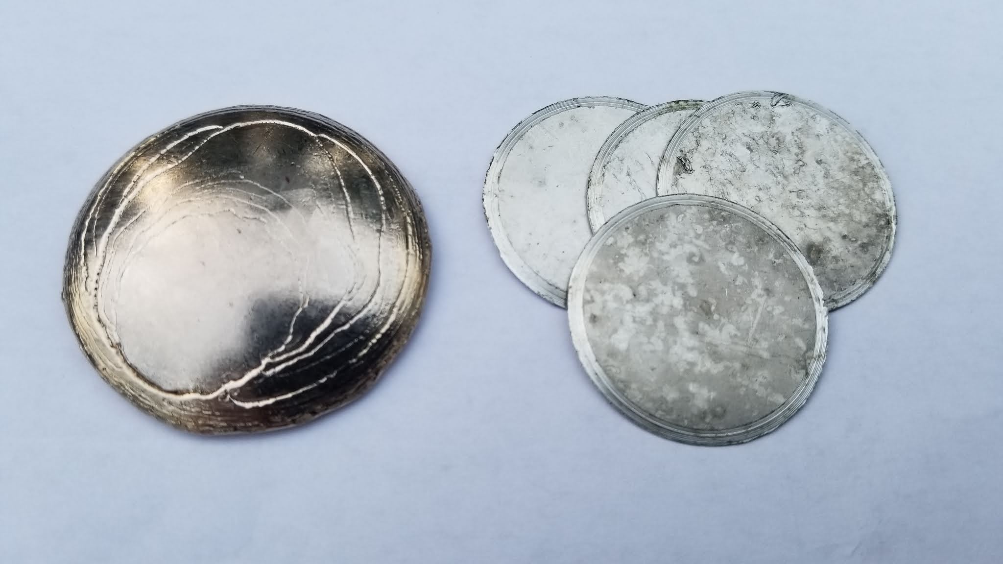
 A 1/16" thick Bismuth metal disk (on the left) and the Cadmium metal disks as part of the graded shielding for the very bottom of the sample chamber. The goal is to absorb as much as possible of the low energy XRF induced by the gamma rays in the lead shielding.

 Look inside the detector cavity of the main shield.


 Decay Scheme of Co-60


My modified scintillation detector.
I took apart a commercial Sodium Iodide (NaI(Tl) Scionix-Holland) detector from an Exploranium GR-135 and reworked the whole Dynode Voltage divider circuit. In addition, I installed a bulkhead BNC connector on the cap of the housing - the original detector just had cables coming from a rubber grommet on the side of the cylinder.
These are older but quite nice, all-around, spectroscopy-grade detectors that can be found used as part of surplus sales and are not outrageously expensive as most such detectors - mine came from a "Border Patrol contract" GR-135 unit.
I was lucky to find a unit with ~7.5% resolution at 662 keV - while this is typical of these detectors, if the device was abused, crystal was cracked or moisture got inside, performance will greatly deteriorate, or it could be rendered completely useless for Spectroscopy.
The scintillation detectors are very expensive and fragile devices and should be protected at all times (!!!). The housing must be sealed air-tight as ambient moisture will destroy the crystal, any ambient daylight will destroy the PMT when bias voltage is applied! Tiny light leaks will spoil the measurements, mechanical shock (even a simple drop) can damage both, the crystal and break the glass-envelope PMT (which is a vacuum tube in an essence), bias over-voltage will shorten the PMT's life, etc.
I am storing my detectors in a well-padded Pelican case with some Silicagel bags to absorb moisture.
One should pay attention at the cosmetic condition (as everything is factory sealed anyways) when buying a used and/or untested detector as this usually can show evidence of rough handling. The bottom, aluminum part where the crystal is encapsulated should not have any dings (!) or deep scratches.
Considering how fragile these devices are, the risk of buying a damaged / dropped detector is very real!
The original detector as just removed from a GR-135 unit cannot be used directly with GS-USB-PRO - the Dynode Voltage Divider must be completely reworked.
The role of the PMT voltage-divider is to provide HV for the tube's Cathode-to-Anode bias and gradual voltage to all of the dynodes in-between, as each dynode receives higher voltage than the preceding one, thus progressively increasing the gain with each consecutive dynode stage (Hamamatsu R980 PMT has 10 dynode stages). This process achieves multiplication of the electrons in an "avalanche effect" until all electrons are collected by the anode. The overall multiplication factor follows the level of the High Voltage bias input.

The original divider in 38B57 is a transistorized circuit and has a number of active components - it is designed to work with the firmware in GR-135 where the linearity is compensated for in the software and tailored for a specific energy range. Such divider will provide very poor linearity if used directly, in a conventional way - a "classic" PMT dynode voltage divider is needed.

This is the original circuit on the back of the PMT. Cables are fed thru a sealed rubber grommet on the side. Easiest way to rework the divider is to completely remove the board. As there is no socket for the PMT and the PMT itself is equipped with wire pins which are not suitable for a socket, all 12 pins must be de-soldered from the PCB. The PMT is a glass-envelope vacuum tube and caution must be exercised when de-soldering. If the stainless steel outer housing is not removed (and it is nearly impossible to be removed non-destructively as it is glued extremely well), installing the board onto the PMT leads can be quite difficult but not impossible - it took me about 20 min to re-align the stiff lead wires with the PCB holes. I just didn't want to even try to remove the main detector housing - it is glued and sealed to the crystal housing with a very strong adhesive, and I just didn't like the idea of disturbing the assembly.
Caution! The PMT in 38B57 is glued and sealed directly to to the front of the crystal inside the lower aluminum housing and it can not be replaced if damaged without destroying the crystal. Basically, other than the voltage divider, nothing else in these units is serviceable. It is an all-in-one type design with no separate encapsulation for the crystal.
Alternatively, one can work on and rebuild the voltage divider even without removing the original board - I did it for another detector and it was not difficult at all.


The reworked Dynode Voltage divider, using metal-film, high-voltage SMD resistors and HV ceramic 3kV capacitors. R=2M, 2R=4M for a total of 24M. All resistors are within 1% tolerance and actually better - I purchased extra resistors and used a LCR bridge to select and match 10 resistors as close as possible to the designated value and to each-other. The reason for using 2MOhm resistors in the divider instead of 1M, often used in lab setup PMTs is to minimize the voltage drop as the GS-USB-PRO's HV Power Supply is not incredibly "stiff" as a lab supply so a bit higher impedance helps .
I was able to use the old pads and traces with only one additional small jumper-wire. BNC connector was installed on the cap, sealed and connected via small diameter short coax to the PCB. Unfortunately there is not enough space for an SHV type connector with its longer, insulated center conductor lead. The PMT's Cathode, Mu-metal tube shielding and the detector housing were all grounded together.
The resistors values in the voltage divider are specific for use with GS - the overall impedance is too low if used as a simple scintillation probe with a battery operated Ludlum-type meter for example - in such case 120M divider is expected with R=10M and 2R=20M correspondingly.

If this detector is modified for use as a standard scintillation probe (with a survey meter like Ludlum for example), R should be 10M with 2R = 20M - just like on the schematics. Higher impedance is needed in such case for these battery operated meters as their voltage supply is not as "stiff".
One thing I was very pleased to see is that the PMT inside the stainless steel housing had a separate Mu-Metal magnetic shield - both, shield and housing are also internally connected to GND.

My Gamma Spectacular GS-1525 NaI (Tl) detector.
This detector offers better resolution (~6.5% FWHM for Cs-137 / 662 keV) then the Scionix-Holland 38B57 (7.5%) using EPIC 1.5" x 2.5" NaI(Tl) crystal and ADIT PMT but at a much steeper price tag (and it ships from Australia). Same bias voltage - 650V is producing higher level pulse signals. This detector is equipped with SHV connector for both bias voltage and signal.
The beauty of this detector is the encapsulated crystal with an optical window and a separate PMT which allows for service and experimentation with various detector components.
2. Detector Driver - This device is the electrical interface between the Detector and the MCA - it usually contains a High-Voltage Bias power supply for the PMT, coupling/decoupling circuit, an adjustable gain pre-amplifier, ADC and a Sound Card USB chip (in my specific case).
I use Gamma Spectacular GS-USB-PRO (www.gammaspectacular.com) as a Detector Driver and this device is great - I love it and highly recommend it! The unit connects to the USB port and powers the detector as well as it provides the analog (external sound card needed) and digital (built-in sound card in GS) interface to the MCA software. It is a highly configurable, flexible and adjustable device. GS-USB-PRO also provides a very nice stable HV bias supply /w voltmeter and allows for super-easy adjustment of the high-voltage to the PMT - range is 0 to 2000V.
I run my detector at 650V - it is a good compromise - lower voltage gives you better linearity but low gain, while high-voltage affects the linearization but gives more gain to pick up weak gamma-emissions (and noise of course). The exact optimal voltage should be determined experimentally because it is tied to the particular condition of the crystal, PMT and voltage divider as well as to the targeted energy range.

All active components of my Gamma Spectroscopy Setup.
The GS-USB-PRO Detector Driver - compact and attractive design. SHV and BNC connectors on the front panel alongside the USB port, analog audio jack and all trimmer adjustments for the high-voltage, pulse shape and volume. On the bottom of the housing there are 2 switches for selecting detector wiring mode and the analog jack mode. The analog jack can serve as an input to connect two units for coincidence measurements. My GS unit is the latest v. 3.2 hardware revision with all modifications to accommodate the Schmitt trigger daughterboard for use with Neutron Detectors.

There is a bright digital voltmeter on the top side of the unit. The trimmer pot on the front is adjustable with a small screwdriver for a range of 0 to 2000V. The voltage readout is absolutely stable and adjustable to 1V resolution.
3. MCA or Multi-Channel Analyzer - this can be either a stand-alone external hardware unit or a software component running on a PC. I use the software version - actually a few of them, running together on my laptop - PRA, Theremino MCA and BecqMoni (all free software btw.). Each application has its own pros and cons but fortunately they can run simultaneously on the same machine and listen to the same detector.

Theremino MCA displaying a typical Thorium-232 spectrum.

PRA displaying the results from a Lu-176 (LYSO Crystals) Gamma-Spectrum Analysis.
If the Detector is the "heart" and the Driver is the "spine", then the MCA is the "brains" of the operation.
What the MCA does is pulse detection and acquisition thru the sound card input, pulse filtering to reject malformed and distorted pulses by evaluating the pulse shape, classifying the pulses by placing them into "bins"/channels based on their energy and building a number of histograms and graphs out of the processed data.
Energy calibration is done using calibration sources, allowing the software to correlate known gamma energies to specific channels. The software will also perform Gaussian detection over the Pulse Height Histogram and detect peaks as potential Regions Of Interest (ROI). A variety of tools such as Detector Resolution Compensation and filtering can be used to process the acquired spectrum.
The software is not extremely complex but requires a good bit of understanding and knowledge in Gamma Spectroscopy and pulse detection and acquisition. Very little is automated and manual evaluation of the spectrum with the help of reference sources is generally needed to identify unknown radio-nucleoids.
4. Interconnects - these are mainly the cables connecting the Detector to the Detector Driver and cable connections for audio and USB to the computer.
GS-USB-PRO supports "Single cable" configuration (which is what I use) where HV bias and signal pulses share the same coax cable) as well as "Dual Cable Mode" - 2 separate lines - one for the PMT HV bias and one for Signal. There are 2 connectors on the front - in a "Single cable mode" only the SHV connector is used. In "Dual Cable mode", configured by a switch, the signal is received over the BNC connector while SHV is used for the PMT bias only.
The critical part is the Signal cable as it should be of a high-quality coaxial type with a fairly low capacitance - best is less than 60pF total (with both connectors installed on). Higher cable capacitance widens the pulses (which normally are very short) and makes their shape "mushy", especially the trailing edge.
The high-voltage cable should be done with a properly shielded coax cable, able to withstand up to 2000V without arcing. For anything above 1000V I would use SHV type connectors (rated at 5000V/5A) - regular BNC are not really meant for high voltages. I installed a female BNC connector on my Detector housing so my single coax is SHV-to-BNC as the detector runs on only 650V and there is not enough space for the extra-long SHV type connector..
Cables are part of the calibration chain - i.e. changing cables WILL require a re-calibration.
5. Detector Shielding - for more details on making the Lead shielding for my detector, please see here!

Portable, field deployment

Lab setup

Part of the inner copper shielding is clearly visible inside the main shielding shells. There are additional, removable copper-tin cylindrical inserts (not pictured here). They are made by rolling a "sandwich" of thick copper foil and real tin (pewter) foil into a tube with wall thickness of 1 mm copper on the inside - 1 mm tin and another 0.5 - 1 mm copper on the outside.

Main detector shield (top) and the "large sample holder" (bottom) mated together - the lead thickness is 22mm around the crystal in the main shield or up to 35-50 mm once the outer sleeve shield and (optional) bricks are installed. In the wooden shield-carrier cradle, the main shield assembly is situated over 3/4" thick base of lead bricks and the outer shield (sleeve) is placed over the assembly on lead raisers.
A stack of bismuth, cadmium, tin and copper disks is lining the bottom of the sample chamber. Pictured here are the tin and copper disks.
This is called "graded shielding". A coper-tin-copper sleeve insert is placed on top of the stack lining the walls of the sample chamber. Similar but longer sleeve insert is located in the upper shell, wrapping around the detector assembly.

Outer lead shielding - 12.7 mm of lead thickness.
Nothing beats the looks of an OD Green-colored "canister" resembling device with a bright yellow "Radioactive" sign 😁.

The little removable copper cup on the bottom is used to hold small high-activity samples or calibration sources or it can be used as a "raiser" (when flipped) to bring the sample closer to the scintillation crystal.
6. Calibration Sources - these are extremely important aids for the proper energy calibration of the instrument. Without accurate calibration the measurements are more or less meaningless.
In theory, any strong radioactive source with a known spectrum and activity can work.

By now, I should have approximately 0.736 uCi of activity left in my Cs-137 Calibration Source made in April 2007.
The 1uCi Eu-152 and Co-60 were freshly made in the beginning of August 2020.
The uncertainty of these sources is generally +/- 20% of the specified activity.
Decay Scheme of Cs-137

The "classic" Cs-137 Gamma-spectrum (peak @661.6 keV) is a good mid-range starting point for the calibration process.

Eu-152 Gamma-spectrum with multiple peaks nicely spaced up to 1408 keV.
There are other energies emitted by Eu-172 but their intensities are just a few percent.
This spectrum was produced with "Sum Quantity" feature in PRA

One of my Lutetium calibration sources - 1 gram of 99.9% pure natural Lutetium sealed in the center of 1" plexiglass disk.
Natural Lutetium contains 2.6% (or 26 milligrams in my sample) of the primordial Lu-176 isotope and it produces two very distinctive gamma photopeaks at 201.83 keV and 306.78 keV and an X-Ray (Kα1 Hf) peak at 55.79 keV. There is another Lu-176, weaker photopeak at 88.34 keV. The natural Lutetium metal has an activity of ~51.6 Bq/gram.
This is a fairly inexpensive calibration source with a price of around $8-10 per gram for the pure rare-earth metal.
Lutetium and Potassium Chloride are excellent "air-travel" calibration sources for when bringing the spectroscopy setup to the field - their radioactivity is extremely weak (Geiger Counters will not even register activity), making them completely safe to carry on-board of an airplane. (attempting to board a plane with a Cs-137 or Co-60 source will likely result in a lot of troubles)

11 hours spectrum scan of Lu-176 from 2 LYSO crystals in a Lead castle (with 9 hours background spectrum subtracted). The plot also shows the Sum peak at around 508.61 keV as well as the 55.79 keV Kα1 Hf-176 X-Ray peak.
The 509keV Sum peak occurs due to the coincidence emissions and detection of the 202kV and 307keV photons.
A Detector Escape peak from the NaI in the detector crystal is usually observed at around 26 keV in the Lu-176 spectrum. This Iodine Escape Peak comes from the K-shell of the Iodine when it interacts with higher energy X-rays and the resultant emission escapes the detector. it is located ~28keV (the binging energy of the K-shell electron of the Iodine) lower than the incident photon causing it - in this case the Hf-176 Ka emission at 55keV.
The escape peak is prominent when the energy is below 200keV - because the difference is so small (only 28keV) for higher energies it falls within the main photopeak and it is usually masked.
Spectrogram-wise, there is no discernible difference between LYSO crystals and metal Lutetium.
LYSO crystals are used in PET detector arrays can be found from a number of sources.
In the absence of a proper strong calibration source, for two-point calibration one can use Potassium (K) which has a small amounts (0.012% of all Potassium) of the primordial isotope K-40 with gamma @ 1.46 MeV (actually, I use about 100g of Potassium Chloride (KCl) as my K-40 source) - such calibration takes fairly long time in order to get a good, measurable peak as the activity is pretty low but while doing this, I can also observe the positron annihilation peak at 511 keV as another point of reference for the calibration. Generally it is good to have a good separation between the 2 peaks and to encompass the targeted energy range. Sources like Eu-152 and Na-22 give very good results for energy calibration.
Normally, my first step is calibration with a Lu-176 source (using Lutetium metal or Lutetium-Yttrium Oxyorthosilicate (LYSO) crystals) with gamma photopeaks at 201.83 keV and 306.78 keV, followed by the "classic" Cs-137 (1.0 uCi) disk source at 661.66 keV and the X-ray peak at 32.19 keV. Next is calibration of the high-energy region using 1uCi of Co-60 disk source at 1.173 MeV and 1.332 MeV. As a final step and confidence check and to fine tune the linearity of the detector, I use 1.0 uCi disk source of Eu-152. Europium-152 produces a number of peaks throughout the spectrum and it is a good way to check the overall calibration accuracy.
Thorium (Thorium Dioxide (ThO2) from a gas mantel) also works well to check the linearity of the detector as it has many peaks from daughter products which are spread throughput the useable gamma spectrum to as high as 2614.5 keV (Tl-208)

Natural Uranium test-source.
1" plexiglass disk with a center hole, housing Autunite crystals. The crystals are completely and safely sealed inside epoxy resin. The resin block all Alpha particles - the Autunite activity was around 6000 CPM but after filling the cavity with epoxy, sealing the mineral, it dropped to 2200 CPM.
This source gives a nice "classic" uranium spectrum with Photopeaks of various daughter products.
Collecting background spectrum for subtraction and energy calibration should be done before AND after main spectrum acquisition to minimize effects of thermal drift and changes in the background - this is especially important for low-activity samples.
Conclusion

I love the portability and compactness of my setup - everything fits in 2 Pelican cases and can be carried in the field. One case contains the detector, driver, interconnects, etc. The other case holds all of the lead shielding components (and weights over 70 Lbs!). The calibration sources are stored inside the shielding for transportation.

High-activity sample setup - less lead shielding is generally needed.

Low-activity sample setup - additional lead is added to suppress the natural radiation background and the detector is fully encased (4xPi) in lead.
It is amazing to think that once available only in Scientific Laboratories and Universities, Gamma-Spectroscopy is now affordable and enjoyable for hobbyists and Nuclear / High-Energy Physics enthusiasts!
Special Thanks to Steven Sesselmann for hosting the Gamma Spectacular Science Forum.


20 comments:
Nice Gamma-Spectrum-Analyzer outfit and especially the work you have done with it.
DE K0FF
George Dowell
"Geo"
Hello, I just bought multiple setup from Atom Fast 8850, GQ GMC-600+, GQ GMC-500+, Radex 1503, Radex RD1212-BT & Gamma Spectacular with Scionix Holland Gamma Scintillation Detector NaI(Tl) 38mm and Ludlum 43-5 Alpha Scintillation Probe (CPM only). I'm also getting possibly the very last RadiaCode 101. I'm setting up 3 labs (one in the US & 2 in Thailand for my family) to be able to inspect food/water for radioative contamination.
My question is if you know the lowest level of radioactivity your setup could handle (mine is similar)? Will it be enough to handle down to less than 1 m Bq m−3 to 31 m Bq m−3 per below? If not, what would you do to improve it?
https://pubs.rsc.org/en/content/articlelanding/2012/em/c2em11011c/unauth
The release of radioactivity into the atmosphere from the damaged Fukushima Daiichi nuclear power plant started on March 12th, 2011. Among the various radionuclides released, iodine -131 (131I) and cesium isotopes (137Cs and 134Cs) were transported across the Pacific Ocean and reached the United States on 17–18 March 2011. Consequently, an elevated level of fission products 131I, 132I, 132Te, 134Cs and 137Cs were detected in air, water, and milk samples collected across the United States between March 17 and April 4, 2011. The continuous monitoring of activities over a period of 25 days and spatial variations across more than 100 sampling locations in the United States made it possible to characterize the contaminated air masses. For the entire period, the highest detected activity values ranged from less than 1 m Bq m−3 to 31 m Bq m−3 for the particulate 131I, and up to 96 m Bq m−3 for the gaseous 131I fraction.
Honestly I never tested what is the lowest activity I can get spectrum out of. There is not an easy way to do this - I'll need to have samples with a known low activity.
I repurposed my Scionix-Holland detector to do counting and moved on to the more sensitive and more efficient 63x63mm NaI(Tl)/Hamamatsu R6233 detector ( http://blog.kotarak.net/2021/09/bigger-is-better-or-building-larger.html ).
When you are dealing with very low activities, larger crystal is always a better choice - less high-energy photons will be missed. People routinely pull spectrums from Fukushima soil wit 2-3" crystals.
Another extremely important component to low activity scanning is the shielding. Lead castle - 4pi shielding with a very thick lead wall - 2-3 inches at least and copper inner layer (1/8") is absolutely essential to suppress the radiation background which can drown low activity peaks. I use graded shielding - Lead, Bismuth, tin, cadmium and copper - this helps to suppress the huge Lead XRF photopeak one will usually get with Lead-only shielding.
Finally, for low activity scanning, geometry is very important as well and the use of Marinelli beaker is essential - it places the sample close and around the crystal.
Hi. This is a very informative and excellent piece of work. I have a rather mundane but important issue on which you can likely shed light. I have just started to put together a set up mostly following your road map. I bought a Bicron / Saint-Gobain 1.5M2.25/1.5L NaI(Tl) scintillator detector taken from an Exploranium and it seems this unit is the exact equivalent to the Scionix Holland unit you modified. The unit appears undamaged in any way. The end cap with the wires protruding out the grommet is a one piece cup-shaped cap that evidently is glued in some manner to the rest of the cylindrical assembly. It seems this is somewhat different from the Scionix Holland unit. Can you describe how you removed the end cap from your unit without damage? How did you re-install it? Can you provide any insight on how the Bicron unit might be bonded in this regard?
Hi Frank, on the Scionix-Holland 38B57 the rear aluminum cap is just glued around the edge - the cap has a portion (top) which has the same diameter as the outside diameter of the steel housing and a part of it (around 1/8") is inserted (a tad smaller than the inside diameter of the steel housing). This is where the glue is applied. To remove the cap, I used a sharp utility razor blade and a heat gun - it is fairly safe to heat up the cap as there is nothing right behind it that can be damaged by the heat. After heating it with the heat gun I quickly used the the edge of the blade to insert it in the seam and pry the cap by repeatedly turning and heating the top edge of the steel housing and the aluminum cap. It is a good idea to hold with your hand / feel the temperature of the crystal (bottom part) and make sure that the heat is not reaching it. Crystals are very sensitive to thermal shock and a rapid temperature changes will cause the crystal to crack. The glue on the Scionix detector is not a normal hot glue but still the heat makes it softer and it will give up at some point. To re-attach the cap I used a bit of hot-glue and a self-adhesive copper tape to completely seal the seam. Do not try to separate the crystal from the PMT - on these integrated assemblies, the crystal is not encapsulated but glued directly to the PMT and sealed so any attempt to remove it will destroy the detector.
I just looked at the Bicron / Saint-Gobain detector housing and it is quite a bit different but I would assume the same technique will work. Again.. keep an eye on the bottom 3 inches of the housing where the crystal is located and make sure no heating or significant temperature change is taking place there - a moist towel could be used to maintain the ambient temperature of the housing around the crystal.
You are confirming my initial thoughts. Similar to opening a cellphone to replace the battery, I was guessing. The right amount of heating and then prying open the cover. I experimented a little bit by using a heat gun to determine how hot the cap was getting while holding the xstal end with my bare hand. Your idea of holding a wet rag on the xstal end is good. I am familiar with adhesives and if is used a hard setting epoxy, for example, the heating technique is likely to fail. I think I have to be prepared to sacrifice this unit in order to learn how to get this open. The cap seam is right at where the PM tube ends, so heating has greater risk of damaging the unit in this case. I will post again when I get some kind of result. Otherwise, I will shop for a Scionix unit if this one breaks.
On the 38B57 detector they have used some sort of epoxy around the crystal-PMT assembly as it has to be completely air-tight and mechanically strong but the back cap was no glued with an epoxy. The glue is black in color and with the consistency of semi-hard plastic - it is not normal hot-melt glue but I don't think it is epoxy either. It did take quite a bit of heating indeed to soften it enough but at the back there is just an empty volume and then the PCB is mounted on top of the PMT so it can take the heating as long as you dont let the heat to creep down towards the crystal. The Scionix detector housing is made of 3 parts - bottom aluminum cup housing the crystal, a stainless steel tube around the PMT glued to the aluminum cup (this bond is not possible to be broken safely without destroying PMT/crystal it and seems to be epoxied) There is also a layer of Mu-metal between the steel tube and the PMT and then the whole thing is closed off on the back with glued aluminum cap.
Even though the dimensions and electrical functions may be identical the Bicron package is quite different. There are only two parts, not three as in the Scionix. And the material of the package is a single metal, which very much appears to a non-magnetic stainless steel (austenite). The top cup and the bottom can appear fabricated in a precision manner and not are not simply drawn cans. The end plates (both top and bottom) appear to be welded to the cylindrical bodies in a precision manner evidenced by a seamless appearance and very sharp (small) radius of curvature. The bottom end plate appears to be much thinner than the top end plate evidenced by the sound emitted when tapping on each. If indeed the shell is stainless that would be good in reducing heat travel down the tube toward the crystal. Interestingly I could sense the mu metal wrapping on the PM tube by moving a magnetic against the shell and feeling the force when sliding over the mu metal portion. My main concern is the adhesive bond is made to the phenolic connector of the PM tube and the great amount heat needed may ruin the glass-to-metal seals of the pins, not to mention the force that will be need to pull apart the surfaces while applying heat. That force will be not uniform, but very asymmetric as portions of the seam are pried. My thinking right now is to consider fixturing an arrangement with my Dremel tool and cutting the top end plate off in a precision manner. The fixturing would not be unlike a table saw, for example.
I used my router table for the Dremel and the cap cut nicely off. I am going to guess the case is aluminum based on the ease for the Dremel wheel to cut into it. Inspection suggests this cup is machined, likely from a casting. Tool marks both on the inside and outside. More when I dig into it a bit more.
I have some results to report. First, the Bicron scintillator has been equiped with a conventional voltage divider stack and works well at 550 volts where with GS-USB-PRO it gets all of the peaks from a Thorium mantle is a very proportional manner. Second, I purchased a used Scionix version of this detector. Inspection of this circuit suggested to me that it should work well straight away. The last two stages, which source the most current, have simple voltage follower transistors, a trick often used. The red wire needed to be tied to shield ground. Black and white wires were not used. I found the unit to provide quite narrow pulses, best operated at 550 volts, and the GS-USB-PRO needed the "boost gain" to be raised to 5 in order to get all of the Thorium peaks. The calibration proved to be very linear.
Thank you for the update! I run my 38B57 detector with higher bias - 650V thus the gain boost needed is x1.5 or x2 but as I mentioned I eliminated the active circuit and installed just a standard PMT voltage divider with R value of 2M. The Scionix is a great first detector but due to the age and the integrated construction (no way to observe the state of the crystal) I moved on to encapsulated NaI(Tl) crystals which allow for experimentations with different PMTs and are easier to service and deal with.
If buying a brand-new scintillator outfit, the integral version would give better would give better resolution that the mated pair because of the extra glass causing some extra internal reflection.
That being said, amateurs don't generally go out and buy brand new scints! I tool favor the sealed crystal for many applications and don't like much of anything that I can't take apart just on general principles.
DE K0FF
George Dowell
"Geo"
I've done some searching about graded shielding for gamma spectroscopy, but not finding any good analysis of the process to allow well informed customized/optimized solutions.
The FRMAC Gamma Spectroscopist Knowledge Guide states: For a typical commercial detector shields used in laboratory gamma spectroscopy systems, the graded shield consists of
10-cm Pb, 3-mm Cd, and 0.7-mm Cu, and that tin can be substituted for cadmium.
This is a much simpler shield construction compared to what you are using with multiple materials. Why the more complex design?
I agree that it might be an overkill - I just had these materials at hand. The idea of graded shielding is to add other materials in front of the lead. The lead Ka and Kb lines from XRF are absorbed by metals which have an even lower energy Ka and Kb emissions. Many commercial Gamma spectroscopy shields employ only copper - Cu is great because the Ka is only 8.05 keV and Kb is 8.90keV - below the range of most GS detectors. As you said Cd and Sn are very comparable (Cd is better but toxic compared to Tin). Using both probably doesn't have any significant effect but I had these discs laying around. I added Bi simply because I had it handy as well and was thinking it might partly filter the Pb's Kb emissions but might not be necessary at all and it easy to remove. Regardless the suppression of Pb's XRF seems to be pretty good with the way I have it configured - I am happy with the results and left everything in place until I find a reason to remove the additional grading.
My design uses rolled up sheets of Pb, Cd, Cu. When the configuration is rolled up with a small diameter for a smaller chamber, the dimensions of the walls look exaggerated. When it rolled up with a larger chamber there is a more proportional look to it. The same weight for all configurations, but universal fit as needed. I designed it for portable/field use, in such a way it could be disassembled so I could carry it to the van in pieces.
Geo
Left a comment before reading all of the comments, not just the blog. I see the explanation for the more complex grading.
I am working up a design for making the main shield unit with a steel paint can (7.5"x6.5") and 2" thin-wall "moonshiners" copper pipe (moonshiner supply outfits are the best source for this. which has a 1.1 mm wall. Use a copper cap on the bottom to make the sample/probe well.
To prepare the graded shield one would pour molten tin over the tube to coat, continue until enough mass has been added to equal the shield thickness desired.
For the lead shield, 2" thick on the side, 1" on the bottom the plan is to use pure lead slugs (from RotoMetals) which are cheap, and a high lead/bismuth fusible alloy (around the boiling point of water) to cast them into a solid mass.
Casting threaded steel rod into the mass to provide vertically and horizontally to give it reinforcement and a place to attach lifting handles (wheelbarrow style). It would weigh about 100 lb.
It would sit on a 1" thick lead disk to provide 2" shielding all around.
An electric lead pouring crucible (bullet casters use them) should suffice for metal melting and pouring needs.
I have everything to build except the crucible and about half the lead. But I probably should wait until I have the actual gamma probe I am going to use just to make sure everything is as I think it is.
Good work!. Is your setup able to measure K40 line?.I have a Scionix NaI(Tl) 2.25x1.5" tube, and I have setup a shield with lead rings of 6cm thick on average. Counts fall from 90 to 5 per second with the shield, but I'm not able to see other than a minute peak for K40, substracting the background on Theremino. Do You know if is possible to see that peak, or is too far away for NaI detector?
yes! it is absolutely possible to see the K40 peak. Due to high energy (1460keV), small NaI(Tl) are not very efficient, and resolution of the peak will be low, but it is very visible - just takes a longer acquisition perios for the peak to show up well. A modified Scionix 38B57 needs to run at between 550V to 650V for good linearity and you'll need to find the best voltage for your unit but the peak should be visible. Add some Potassium Chloride in your test chamber if you are using shielding. Without shielding, doing background the peak will still show up after while. Keep in mind that the peak is always present from the environment when you sample the background spectrum so if you are subtracting background in Theremino, you are basically removing (reducing) that peak.
Thanks for your answer!
I'm afraid of chaging the voltage of my theremino v3.3 pmt adapder, but something odd happens here, as it seems pmt measurements falls quickly after 1300keV or so, as seen in this graphs( the second one with background substracted, a uranium ore spectrum added as reference, taken with same parameters)
https://ibb.co/w7F8FHc
https://ibb.co/JFyZXMv
Do you know what the peak at 1250keV is? Although i live in Europe...I doubt it's europium...;-)
Post a Comment