The Bialkali photocathode has an optimal response at 420nm wavelength of the NaI(Tl) crystal. The Photocathode is a tad more sensitive than R980. Effective diameter is 70mm which works perfect for me since the crystal I was going to use is 63mm and larger-than-the-crystal photocathode is optimal - no photons will be lost leaking to the sides.
The factory label - P.H.R. (Peak to Height Ratio) is very good at 7.8% but in reality it is better than the label. The listed PHR is measured with some "standard" for the factory test crystal, with Co-57 (122 keV) source and not the "usual" Cs-137 (662 keV) (hence the lower resolution range). It is more or less worst case.
The PMT came with a factory-installed PCB which I removed and then the 3 stand-offs were cut off. I marked the Cathode pin (K) with a silver dot and Anode pin (P) with a beige dot, To the left of the Anode pin is the Grid pin and to the right of the Anode is D8. On the left side of the Cathode pin is D1 and then clockwise all the way to D8 in sequence. The identification of K and P is easy - the Cathode and Grid are the only two pins separated by a single(!) blank space (missing pin)
All VD components - 10 resistors, a cap, lead wires and BNC connector were provided as a kit by iRad Inc.
A 20M resistor is connected between Cathode and Grid and another 20M between the Grid and D1. Starting with D1, eight 10M resistors are connected between each Dynode (D1 to D8) and between D8 and P.
The resistors are with precision of 1% tolerance and were all checked with an LCR bridge.
Total impedance of the VD is 120M which should be a good choice for battery operated HV supplies which are not as "stiff" as the lab-grade ones.
10nF / 2kV filter capacitor is installed between D8 and GND (Cathode effectively). The leads of the resistor are kept as short as possible. The A and K leads are made of silver-plated Teflon insulated stranded wires inserted in a second Teflon sleeve.
Schematic diagram of the 8-stage Voltage Divider used.

The machined plastic cap came from iRad Inc. as well.
A BNC connector was installed on the cap and connected with 2 silver-plated Teflon insulated wires. I drilled a small hole on the side of the cap for the grounding lead for the Mu-metal Shield. The hole and wire were sealed on the inside with black RTV sealant after the wire was soldered to the BNC's ground lug.
For anyone interested in PMTs and technical details, Hamamatsu published the most comprehensive document I've seen on the subject - The PMT Handbook.
The NaI(Tl) scintillating crystal
Larger crystals have better stopping power resulting in overall better efficiency and this affect mostly the high-energy gamma response.
My NaI(Tl) crystal was purchased on eBay and came from Ukraine. The 63mm x 63mm crystals out of Russia or Ukraine (essentially made in Soviet times) seem to be currently very popular on eBay and they tend to produce excellent results.
Date code is Dec 1987, most likely made in USSR.
The crystal is hermetically sealed in an aluminum canister with an optical glass window and surrounded by reflecting material. The size of the crystal is 63mm x 63mm. The outside diameter of the aluminum can is 71.1mm.
The crystal looks pristine!
There is a lot of junk sold on eBay - cracked crystals, failed seals, yellowing or cloudy crystals etc.
One need to very carefully choose what they are buying - some of the garbage crystals I've seen are not even good for counting yet sellers ask hundreds of dollars. If you see any blemishes or imperfections these could be signs of trouble and better to stay away! A failed seal will let moisture in and will destroy the crystal over time - NaI is an extremely hygroscopic substance.
Fortunately, my crystal looks perfect as if it was made yesterday - not 30 years ago.
Even when the crystal visually looks great it doesn't mean one will get the best resolution tho!
The Size-adapter / Centering Collar
The outer size of the R6233 PMT is listed as 76 +/-0.8 mm and the outer size of the crystal canister is 71.1mm so there is a net difference of ~5mm.
I wanted to center the crystal to the photocathode and have some reliable way to keep it centered while taping the assembly together so I decided to design a centering collar. The collar will serve as a mechanical protection for the optical interface area.
The centering / size-adapter was designed with Autodesk TinkerCAD.
The adapter was printed with conventional filament 3D printing technology.
The bottom portion for the crystal was originally very tight - there was a small "shrinkage" of the print in this area - about 0.5 mm total so I had to sand it until the adapter can slide freely around the crystal.
"Dry fit" of the three components.
The purpose of the "fingers" on the adaptor is to be able to tape it or glue it to the PMT and secure it reliably.
During the assembly, the adapter should fit tightly around the PMT but it should allow the crystal canister to move freely ("float")
The inside area where the transition from one ID size to the other ID takes place is tapered for the glass edge of the PMT. The adapter will center the optical window of the crystal canister exactly to the Photocathode area, while providing both, mechanical stability, shock protection and light-proofing of the interface area.
Optical Assembly
An edge reflector was applied around the front edge of the glass. On this PMT, the photocathode wraps around, to the side for a few millimeters and a reflector in this area will bring back photons otherwise escaping thru the glass edge. I used a couple of turns of white Teflon tape and a layer of pure white PVC tape around the edge and then the whole PMT was light-proofed with the cap, taped securely as well.
For optical interface medium, I used crystal-clear silicone fluid with viscosity of 100K cSt. It is sold as Differential fluid for high-end RC cars. Consistency is much thicker than honey but flows and spreads nicely and it is absolutely transparent.
I started by applying an air-bubble-free drop of the fluid in the center of the window and pressing the PMT firmly on top.
I worked the PMT with large circular movements while pressing downwards for a couple of minutes, overlapping the edge as much as 1/3 the diameter of the window, until any excess fluid squeezes out from the edge and only a super-thin smooth layer is left, covering the entire glass. This process shouldn't be rushed and excessive force can damage the PMT and/or crystal so extreme caution is in order.
I did notice about 0.2% improvement in FWHM resolution vs. the usual optical silicone grease, probably due to eliminating any possible air pockets / bubbles.
I also experimented with a 60K cSt fluid in the past with excellent results but the thicker 100K fluid has less chance for run-off.
The purpose of the fluid is to eliminate glass-to-air and air-to-glass transitions and reduce the refraction and reflection from the surface of the glass - this makes for an optimal interface between the crystal and the photocathode.
Every time a photon reaches a glass-to-air surface it can be either reflected back or refracted in some direction. The optical fluid substitutes any air gap with almost the same refractive index medium as the glass, thus reducing light scattering and loss.
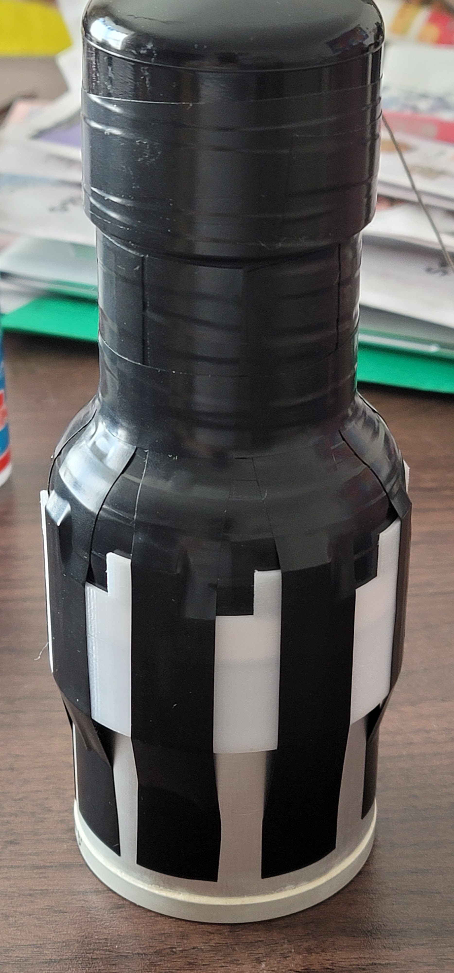
I placed the collar around the crystal before I applied the silicone fluid and mated the two glass surfaces. When I was satisfied with the quality of the interface, I simply pulled up the collar while adjusting the PMT's position and pressing it down to the crystal canister. The entire optical assembly was taped together using electrical tape (3M 88 tape). I started with 8 pieces of tape stretched as tight as possible along the length of the assembly from the crystal's cylinder to the top of the PMT. This "pulls down" the PMT to the crystal with a slight pressure.
The assembly was then taped all around starting from bottom to top while still applying pressure between the canister and the PMT.
An EVA (ethylene-vinyl acetate) closed-cell foam sleeve around the neck of the PMT tube serves as additional mechanical shock absorber and also increases the diameter of the neck which helps later with the installation of the magnetic shielding.
Mu-Metal Shielding
Electrons just emitted by the photocathode can easily be deflected by an external magnetic or electric field and miss the grid and the dynode cascade. The effect of magnetic field deflection on the electron's trajectory is worst when the field is parallel to the photocathode. Earth's own magnetic field, while generally weak to affect most electronics devices is still sufficient to cause a deflection for these "freshly emitted" low-energy / low-velocity electrons. Earth's magnetic field is actually strong enough to cause deflections even in the dynode stage so good magnetic shielding must be provided for the PMT. If stronger magnetic fields are expected, than soft iron shield in addition to the Mu-metal is highly recommended.
The Mu-Metal shielding was constructed in two parts. The sheets of Mu-Metal with self-adhesive back were sourced from iRad Inc. but they can be obtained from a variety of sources.
Two strips were prepared with numerous cuts / "fingers" to fold around the PMT's profile.
The top portion of the Mu shield was wrapped around the neck area of the PMT over the neoprene sleeve in 2 turns and the bottom "fingers" were bent, following the contour of the larger photocathode area.
The bottom part of the Mu-shield.
About 1.5 turns of Mu-metal with "fingers" bent, over the top portion of the shield, overlapping and covering all gaps.
This, second part of the shield extends at about 5mm beyond the photocathode and overlaps the top edge of the crystal - it is the more important part of the shielding as it covers the area between the Photocathode and the Grid.
If the detector will be exposed to stronger magnetic fields, more shielding should be added especially in this area.
The grounding lead from the cap is folded and soldered across the Mu-metal collar.
When grounded, the Mu-metal shielding doubles as electrostatic shielding - electrons can be deflected by electrostatic fields just as well and draining any electrical charges accumulated on the surface of the tube can be beneficial.
Final Assembly
Another thin EVA foam sleeve and a couple of layers of electrical tape were applied over the Mu-metal shielding in order to make it a tight fit around the PMT.
I also fabricated yet another sleeve out of closed-cell EVA foam for the crystal canister.
The foam acts as both, mechanical and thermal insulation - it protects from mechanical shocks and rapid temperature changes of the crystal. It is also a good idea to have this insulation in place for protecting the crystal from a possible thermal shock when the Heat-shrink wrap is applied. There is strict specification how many degrees the temperature should rise over a period of time to avoid stress on the crystal.
Another layer of electrical tape covered the foam sleeves.
Applying the large size heat-shrink wrap is a bit tricky procedure - it has to be heated evenly from all sides so it shrinks equally around the assembly while being careful not to overheat the crystal - a thermal shock can cause it to crack if heating is happening too rapidly.
I did the entire process with little breaks to allow the temperature to drop and slowly equalize as I was heating the heat-shrink sleeve with my heat gun.
The bottom closed-cell foam sleeve was closed off with a thin sheet of the same material, protecting the bottom face of the aluminum canister before the heatshrink was applied
The finished detector came out quite nice and solid.
I still might try to fabricate an outer shell aluminum casing for it, just to make it "bulletproof"
The "Fat Man" codename was changed to Da Gamma Bee II / DGB-2525
Conclusion
After waiting sufficient time for the Photocathode to "calm down" from its excited state due to being exposed to daylight during the assembly I started testing the detector first in counting mode just to make sure the VD circuit is all good!
(!) A word of caution - PMT should never be powered up when exposed to ambient light - this will absolutely destroy the photocathode in a matter of a second.
For reference - this is the background count measured with my VD-modified Scionix-Holland 38B57 - 1.5" x 2.25" crystal and R980 PMT (counter is set to x100K range)
The newly built detector shows more than 2 times increase in the background radiation count. The counter is set to the x100K range so the reading is approx. 20K CPM.
The background measured later with PRA was ~270 CPS or 16.2K CPM but this is normal as PRA rejects malformed pulses, not matching the sampled pulse shape so count will be a bit lower as only pulses good for GS are sorted.
Testing was done at 650V
A quick Gamma Spectroscopy plot of Cs-137 and the results are fantastic - a really nice and clean plot with resolution of 6.53% FWHM at 662keV!Such resolution is more or less as good as it gets for these larger NaI(Tl) crystals.
I used Gamma Spectacular GS-USB-PRO PMT driver set at 650V.
The linearity at this voltage seems very good too - I didn't have to use any Audio Gain factor and all peaks showed up in the right bins indicating that 650V is nearly optimal. In Theremino MCA the Energy equalizer stayed in the same state as before, adjusted after linearity testing and optimization of my other DIY detector. Only the Energy trim had to be adjusted a bit. This is very good sign!
"Fat Man" and "Little Boy" in their carry case. I built these detectors for the fraction of the cost of a commercial detector, getting the same performance. Interestingly enough the cost of the two is very similar regardless of the size difference.
A new member joins my family of scintillating detectors!
(L-R) Da Gamma Bee I / DGB-1531 with 40 mm x 80 mm crystal and Hamamatsu R980, Da Gamma Bee II / DGB-2525 with 63 mm x 63 mm crystal and Hamamatsu R6233, modified Scionix-Holland 38B57 with 1.5" x 2.25" crystal and R980 PMT and Gamma Spectacular GS-1525 with 1.5 x 2.5" crystal and Adit PMT.