A friend of mine and an avid REE mineral collector Charles Young designed some time ago an instrument intended specifically for finding radioactive rocks "in the wild". The design evolved from his initial concept to become a pretty clever and viable solution but at the time it was using audible clicks, very similar to a Geiger Counter.
Charles and I have been talking for a while, exchanging thoughts and ideas about what such specialized radioactive rock hunting instrument should be and what are the features needed to make it efficient. Finally, Charles managed to do something I've been thinking about for years but never really had the time or the proper motivation to dive into! His work was truly an inspiration for me and eventually precipitated as the "Gamma Dog project" as I realized I am not alone in my quest to create a specialized radioactive rock-finder.
With the core R&D work done by Charles, we decide to collaborate in the design efforts and improve both, the hardware and software side in order for this instrument to become the Ultimate Tool for Radioactive Rockhounding.
Currently, on the market there are no such specialized prospecting tools as the Gamma Dog. The glory days of Uranium and REE prospecting are long gone! Consumer grade radiation detection is reduced mainly to inexpensive Geiger counters and dosimeters. The few commercial detectors intended for professional use by geologists are prohibitively expensive for hobbyists yet lacking some very important features.
Geiger Counters are more or less useless for mineral collecting due to their poor gamma ray detection efficiency and commercial scintillators on the other hand, require that your eyes are "glued" to the meter's scale in order to monitor for an increase in the detected rate or you have to listen to a divided click-rate and trying to figure out if the click rate changes, just "by ear", which is a pretty strenuous activity by itself. None of these options were acceptable to us!
We wanted an instrument that is very simple to use, very sensitive, and with an UI that allows the user to focus on the environment / terrain and not on the instrument itself.
The goal was to design an instrument that is really intuitive to use so we can make the activity of radioactive rock hunting more enjoyable than simply staring at a meter and tripping into rocks and branches, while waiting for the needle to jump or a number on a digital display to change.
Meet the γDog!
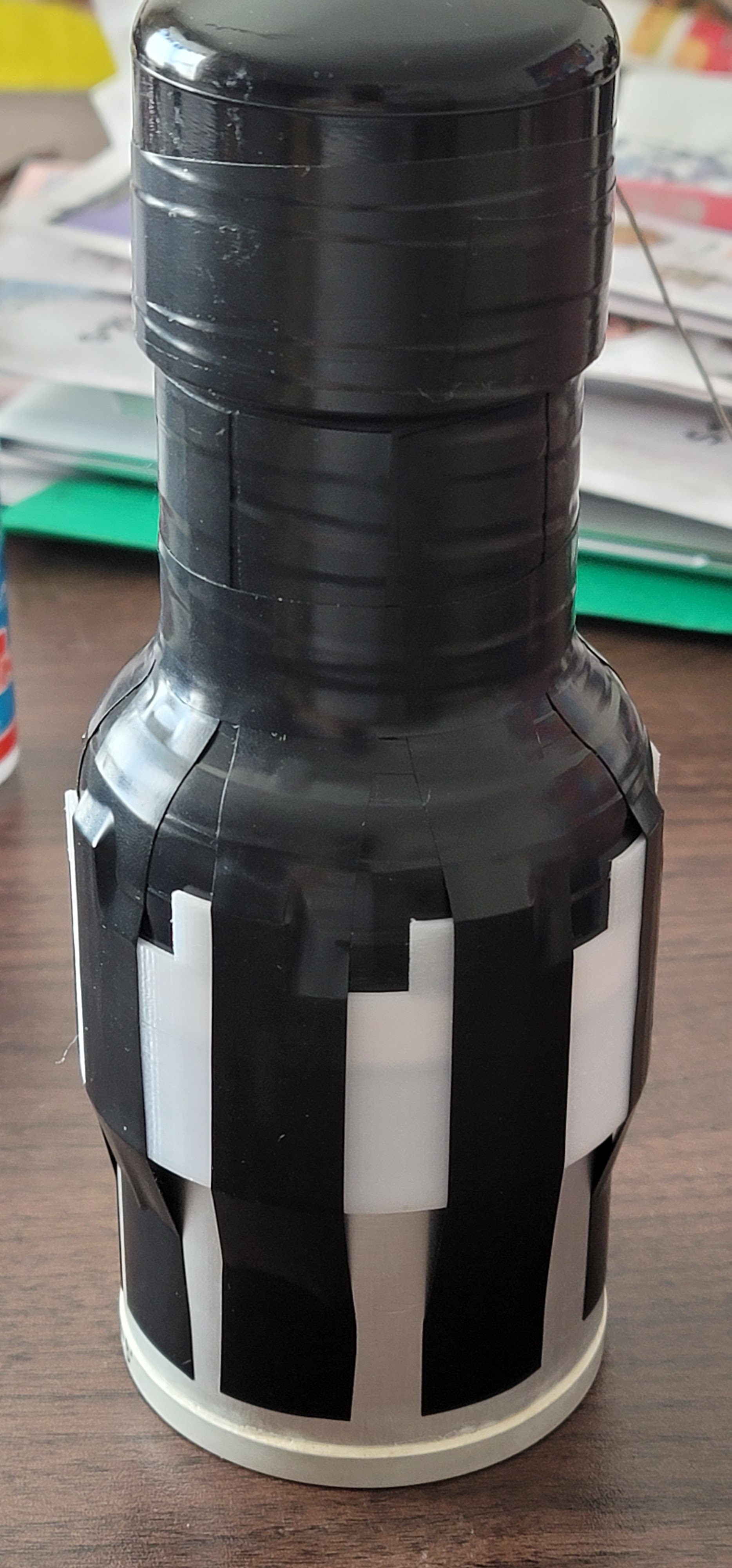
The instrument's housing is a 14.5" long, 4" diameter ABS plastic cylinder, a handle, two attachment points and a control panel located on the top end-cap.
Weight is ~5.5 Lbs when equipped with 63mm x 63mm NaI(Tl) scintillation crystal detector.
I think, at presently the instrument's look is a bit ominous, and I'll probably need to dress it a bit with some decals for the sake of the general public. After all, you press a red, backlit button on a big, black, cylindrical object - it beeps and the first thing you see on the display is the radiation trefoil, followed by rapidly changing numbers - I can see how an ignorant or less intelligent person could hyperventilate seeing this.
The 3 major internal components are the scintillating detector, the electronics package (which includes an advanced microcontroller, pulse amplifier and HV power supply, along with other boards and components) and the 6600 mAh LiPo rechargeable battery. There is also a coaxial cable interconnect between the electronics and the detector.
The scintillating detector is heavily padded with closed-cell rubber foam ("Neoprene") to protect the delicate crystal and PMT from any mechanical shocks and vibrations and to provide thermal stability for the crystal.
The housing can accommodate different detectors and LiPo battery sizes - usually 2x18650 cells in parallel (4400 mAh) or 3x18650 cells in parallel (6600 mAh).
The bottom ABS cap is solvent-welded, and it is completely water-tight. The top cap is removable (3x SS Screws) and hosts the entire electronics module and the control panel.
The Latching Relay board (left) and MCU board (middle) are stacked on the motherboard (right) headers. Visible between the MCU headers are the 12-bit DAC and 4K EEPROM daughter boards. The PCB with red solder mask is the HV power supply, pulse amplifier and detector decoupling circuit.
I designed the PCB with AutoCAD Eagle, and the fabrication was done through the OSHPark service - the PCBs came out absolutely superb with a beautiful purple solder-mask and gold-plated pads and vias! Highly recommend OSHPark for small projects - quality, pricing and ordering process is simply fantastic!
The new hardware version expands on the v2 PCB with a second control button for an improved UI, 4K EEPROM for storing settings and internal data and a 12-bit DAC for digitally adjusting the value of the Pulse Height Threshold. A small modification on the MCU board allows the firmware to read the status of the LiPO charge controller IC.
There is an RFI can for shielding the HV circuit with hole to access the HV Adj. Potentiometer - the red board on the right (the RF shield is yet to be installed on this picture).
There are 6 connectors on the motherboard - one female BNC for connecting the scintillator and 5 others for the power source, buttons, display module, amplifier / speaker board and LEDs (4 connectors are mounted on the top side of the board) - not counting the IPX to SMA coaxial connection.
Not pictured here is the latching relay FeatherWing which plugs into the top MCU headers.
Stacking the boards in 4 distinctive levels allows for a more efficient use of space, while staying with the footprint of the 4" end-cap.
A quick demonstration of the "γDog v2 PLUS" prototype and the UI.
Most of the instrument's housing is occupied by the padded scintillator (see the diagram above). There is also a battery "compartment", and the entire electronics assembly is located in the top end-cap. A fixed metal handle with a soft nylon strap handle and a a couple of special finger pulls / attachment points facilitate easy handling and maneuvering of the instrument while searching and digging. The enclosure is sealed and waterproof up to the control panel so it can be partly submersed if needed. The control panel is water-resistant and can withstand occasional splash of mud, water or light rain and it is easily protected with a transparent plastic "shower cap" and a rubber band in case the weather conditions deteriorate severely. There is 1/4" thick Plexiglass bezel protecting the display.
Large (63x63mm NaI(Tl) crystal) Scintillating detector - there is a post on my blog about building this type of detector, but almost any NaI(Tl) / CsI (Tl) / CsI (Na) scintillating detector can be used or even Bicron BC408/BC412 Plastic scintillators are compatible. Detector requirements are: a voltage divider impedance of 50M-120M, common signal / PMT HV bias line and voltage up 1200V - Ludlum 44-2 probe for example is one possible "off-the-shelf" solution. Recommended background radiation rate for the detector should be at least 50 CPS.
It was time to put my newly built large NaI(Tl) scintillator to work.
My large 63 x 63 mm NaI(Tl) detector is the "heart" of the γDog and covers the "traditional" for NaI(Tl) detectors Gamma Rays energy range of 25keV to 3000 keV. The larger the crystal is, the more efficient and sensitive the instrument is going to be - this is critical when looking for radioactive specimens "in the wild", which can have very weak emissions due to the shielding effects of soil and rocks and/or low N.O.R.M. content. Smaller size detectors or scintillating plastic detectors on the other hand are better when searching in tailings piles, mine dumps or inside mines, where the radioactivity is abundant to begin with.
Adjustable, regulated and filtered, boosted High-Voltage Power Supply for the PMT Bias, positive polarity, outputting in the 600V-1200V range with only 4VDC input. The low-voltage supply rails of the HV PS is controlled with a latching relay for a reduced power consumption when the unit is in "Sleep Mode".
γDog's High-Voltage Power Supply and Pulse Shaping Amplifier.
Pre-amplifier with adjustable gain ratio and adjustable pulse shape - rise/decay time-constants as well as decoupling capacitor and load resistor are all hosted on the HV board as well.
Adjustable minimum pulse level detection threshold using a comparator on the input of the MCU to "digitize" the scintillator pulses for counting.
On the scope's screen, the yellow trace shows the already amplified scintillator pulses. The pulses are then "digitized" by the comparator (blue trace) when they exceed the adjustable preset voltage threshold (white cursor trace on the Y axis).
Nordic nRF52840 System on a Chip is the "brains" of γDog.
Nordic nRF52840 SoC (installed on the Adafruit Feather Sense Board) - ARM Cortex M4F processor, 1MB Flash and 256K SRAM, 21 GPIO, 6 x 12-bit ADCs, up to 12 PWM outputs and an array of environmental sensors - Accelerometer, Temperature, Humidity, Magnetometer, Barometric pressure, etc. as well as Bluetooth LE connectivity.
Amplified (Class D amplifier) panel-mounted 1W speaker with manually adjustable volume (digitally adjustable in PCB v4)
3 backlit buttons (Power, Squelch, Display Mode) with indicator LEDs
High-contrast, ultra-low power SHARP Memory eInk graphics display (144 x 168 pixels)
Rugged Micro-USB port (/w protective cap) for battery charging and firmware updates. Use-while-charging with an external 5V USB battery pack is also possible.
Built-in LiPo battery charge controller with 200mA charge current
6600 mAh / 3.7V LiPo Battery (or 3x 18650 cells in parallel) which provides up to 24 hours of continuous run time or 3 days of normal use. Smaller capacity battery can also be used - 2x18650 (4400 mAh) and will still provide more than a full day of continuous operation while reducing the weight.
BLE or Low Energy Bluetooth connectivity for outboard data processing and storage (on a Smartphone or PC)
Configurable BT power levels
Software Features:
There are a couple of novel features which make this instrument different than anything else out there - the count-rate based variable frequency tone feedback coupled with an adjustable level squelch control. Both features are aimed at easy detection and location of radioactive sources.
Listening to slow clicks while trying to adjust to the background count rate in order to detect any changes when radiation is detected is way too strenuous on the brain - changes in the pitch of a tone on the other hand are picked up immediately and very easy to follow. The squelch control on the other hand makes the instrument "vocal" only when needed, near a radioactive source above background level.
Gamma Dog is running on almost 3000 lines of code (firmware V3.9.2)
Audio is main method of feedback via the variable frequency tone and alert beeps.
Super-simple and responsive 2 buttons UI with click, double-click and long-press actions (all with audible feedback) to execute various actions such as Sql Level Adjustment, Auto-Set, etc.
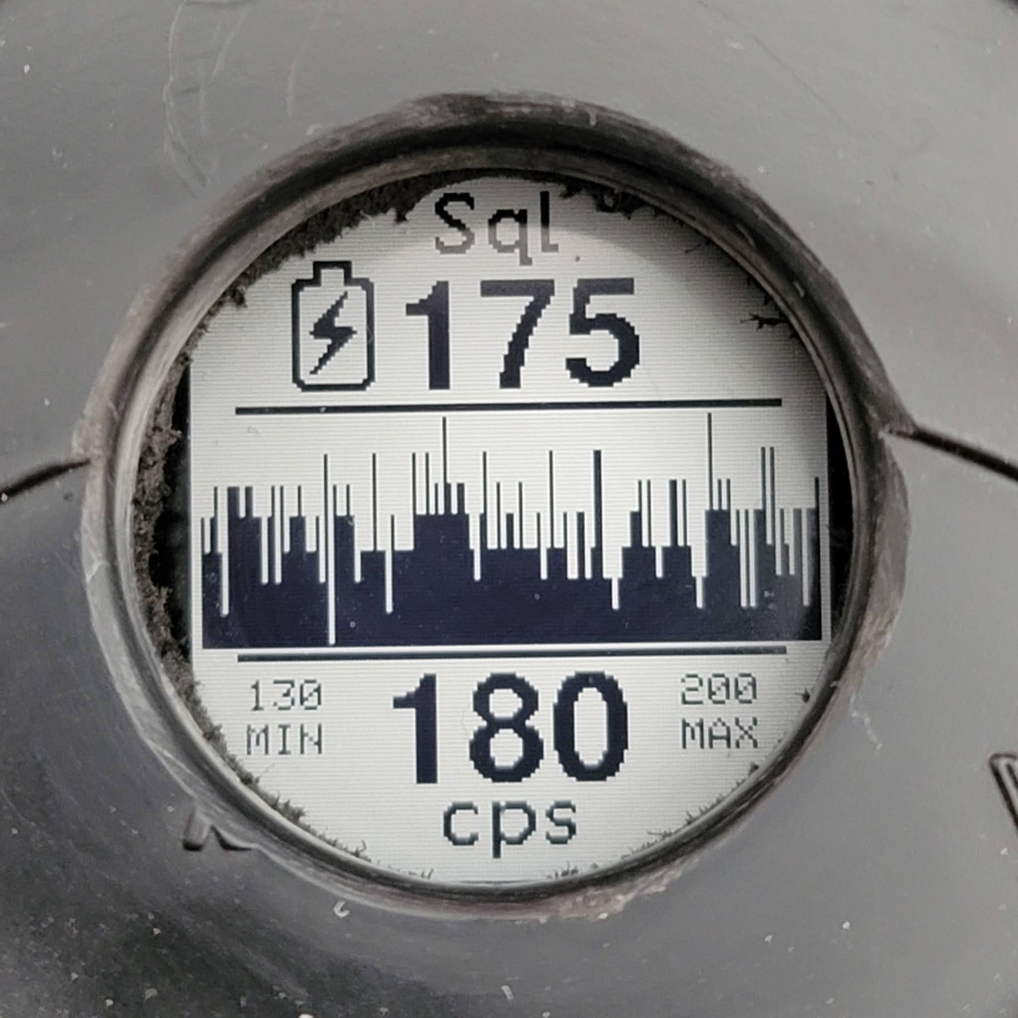
2 user-selectable persistent display modes - Current Rate and Rate vs. Time Histogram.
In the Rate mode, single-click of the Squelch button will increase the squelch level and double-click will decrease the level. Audio frequency will increase 10Hz for each 10 CPS and displays shows numerical count rate.
In the Histogram mode - display shows 140 seconds scrolling count-rate histogram and double-click will toggle between constantly open Squelch and Normal Squelch Control. In addition, in this mode the audio is generated with smaller (5Hz) steps per 10 CPS. This mode can be useful when searching in places with many high-activity sources like mine dumps / tailings. etc. as very high rates will keep the audio frequency half of the rate - i.e., 4000 CPS will result in ~2kHz tone when squelch level is set really low.
2 indicator LEDs - Green Squelch button LED flashes when the number of counts reaches 2x the squelch setting counts and also indicates the startup sequence point for Histogram mode change, Red Power button LED indicates sleep status / HV power off (when blinking) and normal operation (solid glow)
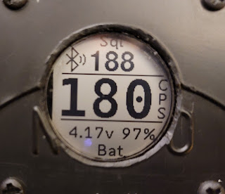
Graphics display shows Firmware version, Internal Diagnostic results and alerts, Current Count Rate in CPS (refreshed every second, resolution 10 CPS) or a count-rate rolling histogram, battery level as voltage and percentage of capacity (refreshed every minute), Current Squelch Level Setting, Count Overflow and Low Battery Alerts.
One of my contributions to the project was the development of the display interface and the firmware code for it, including the UI. γDog PLUS uses 1.3" Ultra-Low Power SHARP Memory display (144 x 168 pixels, same kind as the one used in the Pebble Watch). The display is a very high contrast eInk type, super-easy to read in direct sunlight, recessed in the front panel for mechanical protection and it shows useful information improving on the ergonomics and the interaction with the instrument.
Data on the display is refreshed every second for the Count Rate readout and every minute for Battery-related information.
Battery Voltage, Current Battery capacity and Internal Diagnostics Status
Internal Temperature and Relative Humidity
Internal diagnostic routine reports over-temperature, water intrusion (by measuring the internal air humidity level in the enclosure) and various levels of the battery condition - both visually, on the display and with a series of beeps.
Audible and on-screen "critical battery level" reminder - every minute when voltage drops below 10%
On-screen Charging / Charge Complete Status Indicator
Complete bootup time from Power button press to Ready to use is 12 seconds.
An Advanced Accelerometer-based PMT / Battery saver will shut down the High-Voltage Power Supply and the pulse pre-amplifier after 10 minutes of inactivity (no instrument movement) during normal operation or after 1 minute while charging the battery overnight. The normal operation resumes within 1 second of the instrument detecting a physical movement (for an example - picking it up). During normal operation the red power LED glows solid and blinks when the instrument is in Sleep Mode. I designed this feature with the use of a latching relay to further save power. Going in and out of sleep mode is accompanied by audible feedback (descending or ascending tone chirp). Current draw drops from 70 mA to 10 mA when the HV supply is powered down. The DAC is also powered down during sleep. There is also selectable "No Sleep" mode as well as "Charge and Sleep" mode.
Auto-Squelch Set will sample and establish the squelch trigger level at the current sampled background radiation level during startup or when it is activated by the user with a long-press of the Squelch button.
Tone frequency generation is set always to begin at the current squelch level and frequency always starts low when the squelch opens, regardless of the current rate or range of operation - this allows for the instrument to operate in a comfortable for the human ear frequency range regardless of the current measured count-rate. In other words, the lower end of the audio tone frequency range is dynamically adjusted to begin at Squelch level.
Histogram Mode displays scrolling and auto-ranging relative count-rate histogram
The scrolling count-rate vs. time histogram displays the count-rate history over the last 140 or 45 seconds. The histogram is dynamically normalized to the count-rate range over this period of time.
On this picture, the minimum count rate over the past 140 seconds is the "floor" and max rate is the "ceiling".
Typical background rate histogram (130 CPS to 200 CPS).
The histogram is constantly updated in background at 1 sec interval and always available for the last 140 or 45 sec. It displays current statistics for the span - Min, Max and Average Rate.
High-rate event (2560 CPS) (specimen of Uraninite), followed by drop to background level.
The displayed histogram is dynamically normalized every time it is drawn, to show the maximum rate peak which, on the other hand "pushes down" the background level if there is a big difference in rates.
The 45 seconds histogram. This mode should be used when frequent changes in rate take place and can be set with the Config Menu System.
Response to count rate changes with a pre-set hysteresis which prevents the squelch from opening during short rate fluctuations.
Excessive Count Rate / Overflow alert above 10 000 CPS (600K CPM) - the maximum rate is not really limited but the count accuracy will drop when excessively high rates are detected.
Compensated count accuracy for overall error in counting of 0.1% (electronics only)
Test of the hardware and the software counting algorithm. Feeding the input with pulses from a function generator shows that the counting accuracy is spot-on! Maximum error is 10 CPS for rates above 3000CPS.
Test Setup for counting accuracy and pre-amp alignment.
Maximum count rate is up to 17K CPS (~1M CPM) for short pulses (~50 uS). Average pulse length of 100uS will allow count rate of 10K CPS (600K CPM).
Instrument Usage
Sensitivity comparison between γDog and a Geiger Counter - there is no contest! I know it is "Apples and Oranges" comparison but demonstrates why one would want to use a scintillating detector when rockhounding.
UPDATE: development of Version 3 hardware and firmware has been completed. The UI is now using 2 buttons - it was specifically designed to improve the user-interactions and ergonomics if display output is also present.
The UI can now adjust the Minimum Pulse Height Threshold (PHT). This parameter along with another 16 (firmware ver. 4.3) configurable parameters are saved in the unit's EEPROM.
Adjustments to the Minimum Pulse Height Threshold are done using a 12-bit Digital-To-Analog Converter (DAC) providing reference to the pulse discriminator and displayed in millivolts (accuracy is better than 1mV). Adjustment is done while the device is running in normal counting mode - this way the result of the adjustment can be evaluated immediately.
There are UI coarse and fine steps while changing this value and "Quick Set" preset.
During PHT calibration, 59 keV X-rays from an Am-241 source are used and the PHT value is lowered until the count rate increases rapidly, setting the minimum Gamma energy to which the instrument will respond.
Additionally, there are 17 (for F/w 4.3) items in the Configuration Menu as well as a "Reset to Defaults" feature which re-writes the EEPROM with the factory default values.
The Version 3 hardware installed in the front panel cap.
Only 2 connections are needed to the body of the instrument - coaxial cable with BNC connectors to the detector and a connection to the LiPo Battery pack.
Current draw for the v3 hardware is 68mA during normal operation mode with Squelched audio and only 10 mA during Sleep mode.
The BLUE button is the Squelch Control (UP/+), the GREEN button is Display Mode and Squelch Control (DOWN/-) and the RED button is the power ON/OFF switch. The user now can toggle and latch the state of the squelch system to ON (normally closed) or OFF (continuously opened) by a double-click of the BLUE button.
Squelch Auto-Set is activated by a Long-Press of the BLUE button.
Long-press on the GREEN button switches between RATE and BAR GRAPH mode, and double-click action toggles between Normal Squelch and Assisted Squelch Auto-Set Mode (ASAS).
Version 2+ prototype, display and one button UI (pictured on the left) and Version 3 - finalized hardware design, UI is using 2 buttons, each with 3 functions - one of 6 commands is available at any given time (pictured on the right).
Bluetooth connectivity
Gamma Dog is equipped with a Low Energy Bluetooth connectivity (BLE).
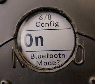
Bluetooth can be enabled/disabled from the configuration menu. On startup, Gamma Dog will automatically start advertising, waiting for connection.
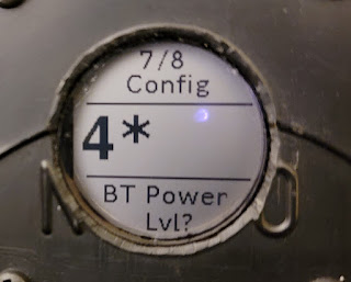
5 levels of BT Tx Power can be set from -20dBm for level 1 up to +8dBm for Level 5.
This menu item is context-sensitive and will show up in the menu only if BT is enabled.
There are two different BT icons, indicating in total 4 different states of the link - whether there is a currently active connection or not and whether BT data streaming is on or off.
Double-click of the Squelch button toggles the data logging on/off and the BT icon blinks showing Data logging is in progress.
Data logging is automatically suspended during Sleep Mode and resumes on wakeup.
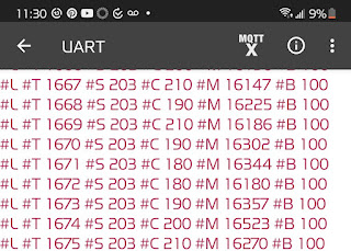
A string of parameters is broadcasted over BT every second and includes various internal parameters, detected current Count Rate and Squelch Level. Each data set includes a rolling counter as well.
Currently, the data can be received with the free Bluefruit Connect App in UART mode or Plotter mode. Commands can be sent back to the Gamma Dog to toggle on/off the logging mode and to stamp "Waypoints" with GPS coordinates.
There are plans for development of a companion Cell Phone App which will store the received data while stamping each set with the current GPS coordinates and a timestamp. Parsing this data and converting it to Google Earth KML/KMZ format would be next logical step. Overlay over the terrain showing the path with current rate and "waypoints" of found minerals will be a pretty powerful and useful prospecting tool.
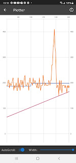
The Bluefruit Connect plotter mode shows Count Rate vs. Time Graph (orange) and Squelch Level changes (blue).
Firmware Update v3.7:
- Added a menu-selectable Sleep & Charge mode - useful to charge the internal battery of the instrument from an external power source (car) or battery pack while in constant motion - during hiking or a car ride when the constant movement otherwise will prevent it from going into Sleep Mode. When this mode is activated, the Gamma Dog will startup normally, it will Auto-Set the Squelch level, but it will fall to sleep unconditionally within 12 sec of startup. The device will not wakeup due to motion in Sleep & Charge mode. Pressing any of the two buttons is the only way to wakeup it up and resume normal operation.
- Added Automatic Squelch Auto-Set (ASAS) mode. Useful as a "Smart Searching mode" while moving through areas with different radiation background levels. This feature reduces the need for manual squelch auto-set when searching. When this mode is activated, the Gamma Dog will automatically execute Squelch Auto-Set if:
(a) The Squelch has been constantly closed for a predetermined amount of time (menu selectable 30/45/60 seconds) AND the set squelch level is more than 100, 150 or 200 CPS (menu selectable) higher than the currently detected rate. This condition occurs when squelch has been set in a "hot area" and then the instrument transitions to an area with lower background levels. The ASAS mode will normalize the squelch level bringing it closer to the current rate thus removing the large gap which occurs between the current rate and the squelch level (a situation which otherwise will make the squelch less efficient and and will necessitate a manual Auto-Set)
(b) The Squelch has been constantly open (30,45 or 60 seconds - menu selectable) and the detected rate does not peak higher than 25% to 150% (menu selectable) of the currently set Squelch Level. This condition occurs when Squelch is set in low background radiation area and a transition has been made to a "hot area" where the higher background keeps the squelch constantly open. Again, the Auto-Set will normalize the squelch level.
If a specimen is being located causing the squelch to stay constantly open but also detecting more than pre-set level of spike in the current rate, this will reset the timer in order to prevent an auto-set while trying to pinpoint the location of the source.
Each of the two timeout timers will reset if a corresponding change of the squelch status occurs.
Firmware Update v3.8:
- added a menu item to set Smart-Squelch timeout - 30, 45 and 60 seconds
- added a menu item to set Smart-Squelch Closed tolerance Level:
4 levels from 100 to 250 CPS in 50 CPS steps
- added a menu item to set Smart-Squelch Open Reset Level:
rate peak will reset the Timeout timer if exceeds the squelch level by 25%, 37%, 50% and 62%
- added 2 more audio frequency modifiers - x0.5, x1, x1.25 and x1.50
- added "Charge Completed" battery indicator
- various code optimizations, improvements and fixes
The Gamma Dog family.
Firmware Update v3.9:
- added "Auto Audio Frequency Multiplier" - activated with the menu system, in this mode the audio frequency multiplication factor will automatically and dynamically be adjusted, based on the difference between set squelch rate and current rate. Change is done in 3 steps - 100-125%, 125-150% and > 150%
- added a warning msg if the USB charging cable is plugged in but the power button is not pressed - the instrument will halt the bootup and will wait for a power switch activation. The "stop and wait" point prevents the instrument from startup if nominal voltage is not present on the power rail.
- reworked the power-saving / sleep mode logic. Now the instrument will start up with normal Time-out delay (duration is set via the config menu system). Gamma Dog will only switch to the short 1 min Sleep Timeout if it detects that a charging cable is plugged in. Disconnecting the cable will cancel the short time Out. If no movement is detected 30 sec to 1 min after the charging cable is plugged in, Gamma Dog will fall asleep. Waking up the instrument will restore the normal timeout even if the charging is still going on - this allows for normal operation when charging in the field with an external battery pack. This, more elegant solution is possible by monitoring the status of the on-board charge controller.
- added startup shortcut to "Sleep and Charge" Mode in addition to the menu selection
- added a menu item to change the Display Color scheme - Normal (black on white background) or Inverse (white graphics on black background)
- added second, fast histogram mode - menu-selectable histogram now will display the rate for the last 140 or 45 seconds.
Quick demonstration.
Note: The instrument described in this blog is NOT THE SAME as the Gamma Dogs sold by Charles Young. It is a more advanced and feature-rich version of the Gamma Dog that Charles makes and sells.
Early in the development process Charles and I branched in our design strategies. Charles develops a simpler, less expensive version with very simple UI. I went in the opposite direction and designed my version (called Gamma Dog+) to have a more elaborate set of features and more comprehensive UI.
The most notable hardware features in Gamma Dog+ are the graphic LCD Display, multi-button UI, Digital-to-Analog Converter for setting Pulse Height Threshold, built-in PMT Bias voltmeter, Digital Volume Control and persistent configuration settings stored in NV Memory. It also has a different, more complex HV Power Supply and a more advanced Pulse amplifier.
One should look at my version as "Gamma Dog Advanced" or "Plus" model. The firmware running on the device is also much different, adding various software-based features and customizations enabled by the additional hardware.
In the world of scintillators, larger crystals means more sensitivity - when you have a bigger volume of scintillating material, it can capture more photon interactions and will produce more pulses. High-energy photons sometime can pass thru a crystal without interacting with it and more material in the way means higher chance for interaction.
I've been doing some radioactive rockhounding using a scintillator in counting mode and sensitivity is everything when it comes to finding that one specimen a foot or so deep in the ground, under rocks, dirt and mud (which btw act as a pretty good shielding).
A larger scintillating detector was in order and having excellent results with my first build, I just went right ahead with 63mm crystal and 76mm PMT. This new detector is intended for both, Gamma Spectroscopy and Counting mode when prospecting.
The Photomultiplier Tube
For PMT I wanted a high quality 3" device and Tom from Irad Inc came thru with a very nice, brand new 8-stage Hamamatsu R6233-05 PMT. This device is intended for use in medical equipment (-05 designation) and came with a factory installed PCB which I removed as it didn't serve the GS purpose - the PCB only contains a few components and not a complete voltage-divider. UPDATE: I have built a half dozen detectors with this type PMT and the results have been absolutely great - it is a really good PMT and became my go-to tube for general spectroscopy and counting.
The device is fairly short (only 123mm) and compact for its 3" diameter size. It has 8 dynode stages which are nested tightly in the "neck" portion. A plastic cap on the back insulates the pins.
The gain (2.7 x10⁵) is less than R980 but this is to be expected with 2 dynode stages less - still it is impressive to see that the 10-stage R980's gain is 3.7 x10⁵
The Bialkali photocathode has an optimal response at 420nm wavelength of the NaI(Tl) crystal. The Photocathode is a tad more sensitive than R980. Effective diameter is 70mm which works perfect for me since the crystal I was going to use is 63mm and larger-than-the-crystal photocathodeis optimal - no photons will be lost leaking to the sides.
The factory label - P.H.R. (Peak to Height Ratio) is very good at 7.8% but in reality it is better than the label. The listed PHR is measured with some "standard" for the factory test crystal, with Co-57 (122 keV) source and not the "usual" Cs-137 (662 keV) (hence the lower resolution range). It is more or less worst case.
The PMT came with a factory-installed PCB which I removed and then the 3 stand-offs were cut off. I marked the Cathode pin (K) with a silver dot and Anode pin (P) with a beige dot, To the left of the Anode pin is the Grid pin and to the right of the Anode is D8. On the left side of the Cathode pin is D1 and then clockwise all the way to D8 in sequence.
The identification of K and P is easy - the Cathode and Grid are the only two pins separated by a single(!) blank space (missing pin)
All VD components - 10 resistors, a cap, lead wires and BNC connector were provided as a kit by iRad Inc.
A 20M resistor is connected between Cathode and Grid and another 20M between the Grid and D1. Starting with D1, eight 10M resistors are connected between each Dynode (D1 to D8) and between D8 and P.
The resistors are with precision of 1% tolerance and were all checked with an LCR bridge.
Total impedance of the VD is 120M which should be a good choice for battery operated HV supplies which are not as "stiff" as the lab-grade ones.
10nF / 2kV filter capacitor is installed between D8 and GND (Cathode effectively). The leads of the resistor are kept as short as possible. The A and K leads are made of silver-plated Teflon insulated stranded wires inserted in a second Teflon sleeve.
Schematic diagram of the 8-stage Voltage Divider used.
The machined plastic cap came from iRad Inc. as well.
A BNC connector was installed on the cap and connected with 2 silver-plated Teflon insulated wires. I drilled a small hole on the side of the cap for the grounding lead for the Mu-metal Shield. The hole and wire were sealed on the inside with black RTV sealant after the wire was soldered to the BNC's ground lug.
For anyone interested in PMTs and technical details, Hamamatsu published the most comprehensive document I've seen on the subject - The PMT Handbook.
The NaI(Tl) scintillating crystal
Larger crystals have better stopping power resulting in overall better efficiency and this affect mostly the high-energy gamma response.
My NaI(Tl) crystal was purchased on eBay and came from Ukraine. The 63mm x 63mm crystals out of Russia or Ukraine (essentially made in Soviet times) seem to be currently very popular on eBay and they tend to produce excellent results.
Date code is Dec 1987, most likely made in USSR.
The crystal is hermetically sealed in an aluminum canister with an optical glass window and surrounded by reflecting material. The size of the crystal is 63mm x 63mm. The outside diameter of the aluminum can is 71.1mm.
The crystal looks pristine!
There is a lot of junk sold on eBay - cracked crystals, failed seals, yellowing or cloudy crystals etc.
One need to very carefully choose what they are buying - some of the garbage crystals I've seen are not even good for counting yet sellers ask hundreds of dollars. If you see any blemishes or imperfections these could be signs of trouble and better to stay away! A failed seal will let moisture in and will destroy the crystal over time - NaI is an extremely hygroscopic substance.
Fortunately, my crystal looks perfect as if it was made yesterday - not 30 years ago.
Even when the crystal visually looks great it doesn't mean one will get the best resolution tho!
The Size-adapter / Centering Collar
The outer size of the R6233 PMT is listed as 76 +/-0.8 mm and the outer size of the crystal canister is 71.1mm so there is a net difference of ~5mm.
I wanted to center the crystal to the photocathode and have some reliable way to keep it centered while taping the assembly together so I decided to design a centering collar. The collar will serve as a mechanical protection for the optical interface area.
The centering / size-adapter was designed with Autodesk TinkerCAD.
The adapter was printed with conventional filament 3D printing technology.
The bottom portion for the crystal was originally very tight - there was a small "shrinkage" of the print in this area - about 0.5 mm total so I had to sand it until the adapter can slide freely around the crystal.
"Dry fit" of the three components.
The purpose of the "fingers" on the adaptor is to be able to tape it or glue it to the PMT and secure it reliably.
During the assembly, the adapter should fit tightly around the PMT but it should allow the crystal canister to move freely ("float")
The inside area where the transition from one ID size to the other ID takes place is tapered for the glass edge of the PMT. The adapter will center the optical window of the crystal canister exactly to the Photocathode area, while providing both, mechanical stability, shock protection and light-proofing of the interface area.
Optical Assembly
An edge reflector was applied around the front edge of the glass. On this PMT, the photocathode wraps around, to the side for a few millimeters and a reflector in this area will bring back photons otherwise escaping thru the glass edge. I used a couple of turns of white Teflon tape and a layer of pure white PVC tape around the edge and then the whole PMT was light-proofed with the cap, taped securely as well.
For optical interface medium, I used crystal-clear silicone fluid with viscosity of 100K cSt. It is sold as Differential fluid for high-end RC cars. Consistency is much thicker than honey but flows and spreads nicely and it is absolutely transparent.
I started by applying an air-bubble-free drop of the fluid in the center of the window and pressing the PMT firmly on top.
I worked the PMT with large circular movements while pressing downwards for a couple of minutes, overlapping the edge as much as 1/3 the diameter of the window, until any excess fluid squeezes out from the edge and only a super-thin smooth layer is left, covering the entire glass. This process shouldn't be rushed and excessive force can damage the PMT and/or crystal so extreme caution is in order.
I did notice about 0.2% improvement in FWHM resolution vs. the usual optical silicone grease, probably due to eliminating any possible air pockets / bubbles.
I also experimented with a 60K cSt fluid in the past with excellent results but the thicker 100K fluid has less chance for run-off.
The purpose of the fluid is to eliminate glass-to-air and air-to-glass transitions and reduce the refraction and reflection from the surface of the glass - this makes for an optimal interface between the crystal and the photocathode.
Every time a photon reaches a glass-to-air surface it can be either reflected back or refracted in some direction. The optical fluid substitutes any air gap with almost the same refractive index medium as the glass, thus reducing light scattering and loss.
I placed the collar around the crystal before I applied the silicone fluid and mated the two glass surfaces. When I was satisfied with the quality of the interface, I simply pulled up the collar while adjusting the PMT's position and pressing it down to the crystal canister.
The entire optical assembly was taped together using electrical tape (3M 88 tape). I started with 8 pieces of tape stretched as tight as possible along the length of the assembly from the crystal's cylinder to the top of the PMT. This "pulls down" the PMT to the crystal with a slight pressure.
The assembly was then taped all around starting from bottom to top while still applying pressure between the canister and the PMT.
An EVA (ethylene-vinyl acetate) closed-cell foam sleeve around the neck of the PMT tube serves as additional mechanical shock absorber and also increases the diameter of the neck which helps later with the installation of the magnetic shielding.
Mu-Metal Shielding
Electrons just emitted by the photocathode can easily be deflected by an external magnetic or electric field and miss the grid and the dynode cascade. The effect of magnetic field deflection on the electron's trajectory is worst when the field is parallel to the photocathode. Earth's own magnetic field, while generally weak to affect most electronics devices is still sufficient to cause a deflection for these "freshly emitted" low-energy / low-velocity electrons. Earth's magnetic field is actually strong enough to cause deflections even in the dynode stage so good magnetic shielding must be provided for the PMT. If stronger magnetic fields are expected, than soft iron shield in addition to the Mu-metal is highly recommended.
The Mu-Metal shielding was constructed in two parts.
The sheets of Mu-Metal with self-adhesive back were sourced from iRad Inc. but they can be obtained from a variety of sources.
Two strips were prepared with numerous cuts / "fingers" to fold around the PMT's profile.
The top portion of the Mu shield was wrapped around the neck area of the PMT over the neoprene sleeve in 2 turns and the bottom "fingers" were bent, following the contour of the larger photocathode area.
The bottom part of the Mu-shield.
About 1.5 turns of Mu-metal with "fingers" bent, over the top portion of the shield, overlapping and covering all gaps.
This, second part of the shield extends at about 5mm beyond the photocathode and overlaps the top edge of the crystal - it is the more important part of the shielding as it covers the area between the Photocathode and the Grid.
If the detector will be exposed to stronger magnetic fields, more shielding should be added especially in this area.
The grounding lead from the cap is folded and soldered across the Mu-metal collar.
The two pieces of metal are grounded together with a few small spot-soldering joints. I was careful to minimize the heating in order to avoid melting the electrical tape or change the magnetic properties of the shield.
When grounded, the Mu-metal shielding doubles as electrostatic shielding - electrons can be deflected by electrostatic fields just as well and draining any electrical charges accumulated on the surface of the tube can be beneficial.
Final Assembly
Another thin EVA foam sleeve and a couple of layers of electrical tape were applied over the Mu-metal shielding in order to make it a tight fit around the PMT.
I also fabricated yet another sleeve out of closed-cell EVA foam for the crystal canister.
The foam acts as both, mechanical and thermal insulation - it protects from mechanical shocks and rapid temperature changes of the crystal. It is also a good idea to have this insulation in place for protecting the crystal from a possible thermal shock when the Heat-shrink wrap is applied. There is strict specification how many degrees the temperature should rise over a period of time to avoid stress on the crystal.
Another layer of electrical tape covered the foam sleeves.
Applying the large size heat-shrink wrap is a bit tricky procedure - it has to be heated evenly from all sides so it shrinks equally around the assembly while being careful not to overheat the crystal - a thermal shock can cause it to crack if heating is happening too rapidly.
I did the entire process with little breaks to allow the temperature to drop and slowly equalize as I was heating the heat-shrink sleeve with my heat gun.
The bottom closed-cell foam sleeve was closed off with a thin sheet of the same material, protecting the bottom face of the aluminum canister before the heatshrink was applied
The finished detector came out quite nice and solid.
I still might try to fabricate an outer shell aluminum casing for it, just to make it "bulletproof"
The "Fat Man" codename was changed to Da Gamma Bee II / DGB-2525
Conclusion
After waiting sufficient time for the Photocathode to "calm down" from its excited state due to being exposed to daylight during the assembly I started testing the detector first in counting mode just to make sure the VD circuit is all good!
(!) A word of caution - PMT should never be powered up when exposed to ambient light - this will absolutely destroy the photocathode in a matter of a second.
For reference - this is the background count measured with my VD-modified Scionix-Holland 38B57 - 1.5" x 2.25" crystal and R980 PMT (counter is set to x100K range)
The newly built detector shows more than 2 times increase in the background radiation count. The counter is set to the x100K range so the reading is approx. 20K CPM.
The background measured later with PRA was ~270 CPS or 16.2K CPM but this is normal as PRA rejects malformed pulses, not matching the sampled pulse shape so count will be a bit lower as only pulses good for GS are sorted.
Testing was done at 650V
A quick Gamma Spectroscopy plot of Cs-137 and the results are fantastic - a really nice and clean plot with resolution of 6.53% FWHM at 662keV!
Such resolution is more or less as good as it gets for these larger NaI(Tl) crystals.
I used Gamma Spectacular GS-USB-PRO PMT driver set at 650V.
The linearity at this voltage seems very good too - I didn't have to use any Audio Gain factor and all peaks showed up in the right bins indicating that 650V is nearly optimal. In Theremino MCA the Energy equalizer stayed in the same state as before, adjusted after linearity testing and optimization of my other DIY detector. Only the Energy trim had to be adjusted a bit. This is very good sign!
"Fat Man" and "Little Boy" in their carry case.
I built these detectors for the fraction of the cost of a commercial detector, getting the same performance. Interestingly enough the cost of the two is very similar regardless of the size difference.
A new member joins my family of scintillating detectors!
(L-R) Da Gamma Bee I / DGB-1531 with 40 mm x 80 mm crystal and Hamamatsu R980, Da Gamma Bee II / DGB-2525 with 63 mm x 63 mm crystal and Hamamatsu R6233, modified Scionix-Holland 38B57 with 1.5" x 2.25" crystal and R980 PMT and Gamma Spectacular GS-1525 with 1.5 x 2.5" crystal and Adit PMT.