Tuesday, October 18, 2022

Gamma Dog - Volume Control

One thing that was really bugging me with the Gamma Dog circuit was the original analog audio volume adjustment. 

The MCU swings a digital output pin, driving the amplifier input between 0V and 3.3V. This output is connected directly to a linear (class D) 1W audio amplifier which employs a tiny trimmer-potentiometer for gain adjustment.

To adjust the audio level in the field, first I have to remove the screw plugging the adjustment access hole (everything on the front panel is dust-proof) and then use a small flathead screwdriver to turn the internal trimmer-pot - hardly a convenient thing to do every time I needed to change the volume.

I normally keep the audio level pretty loud (3/4 of full power) as it helps during windy conditions but when it is quiet and one is kneeling right in front of the instrument, digging a hole or trying to pinpoint specimens, the loud tone in your face can get a bit annoying. Sometimes there will be a couple of us using Gamma Dogs near each-other and becomes a pretty loud "concert" so quick volume control is a "plus". Not to mention the "dirty looks" I was getting at indoor mineral shows from ladies looking for "healing crystals" who didn't like the loud, variable pitch tone produced by the instrument. (I guess it wasn't "resonant to their aura" :-)

Solving the issue entirely on the software side without re-wiring the audio circuit and using push-pull between two PWM digital outputs was going to be pretty intrusive, and also I didn't want to use additional timers and CPU cycles just to control the volume, so I decided to implement a simple hardware solution - digital potentiometer control.

The two main candidates - Analog Devices AD5171 (6-bit resolution) and Analog Devices AD5243 (8-bit resolution) digital potentiometers - 10K resistance. Most digi-pots out there, unfortunately are using SPI interface for control.
I, on the other hand, have a number of I2C devices in my Gamma Dog, so I wanted to stick with the microcontroller's I2C interface bus - this saves me the use of an additional digital output for Chip Select (CS) signal needed with the SPI interface.

I mounted the chips on SMD-to-thru-hole adapter boards - Mouser #535-LCQT-MSOP10 from Aries Electronics for the MSOP-10 component (AD5243) and Mouser #485-121210 from Adafruit for the SOT-23-8 packaged (this one was a bit tricky to install as the MSOP-8 footprint on the board is larger and the leads were not overlapping the solder pads but rather just reaching the very edge of each pad)

At the end, I focused on the AD5243 chip - it is an 8-bit potentiometer - this means 256 positions, and the chip has two independent, addressable potentiometers / channels which gives me a lot more flexibility for future expansion. With the 10K version, each step is 39 Ohms.
This IC is also using very low power - drawing about 6uA. 
Here is the Analog Devices Datasheet.

 Prototyping the solution. Added benefit was that I didn't have to write an Arduino library "from scratch" to control it - Rob Tillaart already did this. His library was written for AD5241 and AD5242 but works just as well with the AD5243 as it uses the same command set - only the I2C device address of the chip had to be changed to 0x2F. The I2C bus signals SDA and SCL require pull-up resistors.

The two SMD 10K pull-up resistors and a ceramic 100nF filter capacitor mounted on the converter PCB.

On the board I connected Ch.1 pot's B1 pin to ground and added also 10uF / 16V tantalum capacitor across the power supply rail to minimize any transient disturbance and low frequency ripple.

I designed the digital potentiometer volume control as an add-on board which is inserted inline between the speaker / amp board and the main board's speaker connector. This connector provides signal and power to both, the digi-pot and the audio amplifier. The I2C bus is connected to the I2C bus on the Latching Relay FeatherWing shield with a separate line. 
JST connectors allow for an easy, no-soldering install in the units.

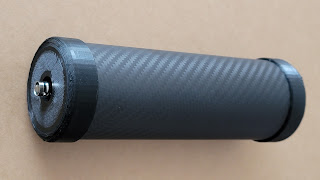
The complete add-on volume control module. The board was placed inside a heat-shrink tube for electrical and mechanical protection. On the left side are the output to the amplifier board pigtail and the input connector. On the right side is the I2C bus connector. The 3-pin input/output JST connectors deliver power to the board and to the audio amplifier.

The add-on board installed in the Gamma Dog. Visible on the right is the I2C bus line going to the FeatherWing Relay pins which are basically a signal feed-through to the MCU board.

 Adding these volume control modules to my fleet of Gamma Dogs was effortless and looks as elegant as an inline add-on board can be. I made 3 such modules.

Crude schematics I sketched while developing the volume control. 
The digital potentiometer acts as an adjustable voltage divider for the output signal. The "wiper" is connected to the input of the audio amplifier. 
Ch. 2 potentiometer is currently unused. 


Writing the firmware support, I implemented two ways to adjust the Audio Volume using the Gamma Dog's user-interface. 
A menu item in the Configuration Menu can select one of 6 volume levels - from a very soft sound suitable for a quiet room to maximum loudness for windy conditions. 6 Volume Levels seems to cover the entire range nicely and I see no need for the "classic" 0 to 10 volume range. This adjustment sets the default volume level of the instrument, and it is persistent (saved in the EEPROM and then loaded on startup).

If the user needs only a quick, temporary adjustment - double-click on the BLUE/UP button will switch the instrument to Constantly Open (Latched) Squelch Mode and the current volume level will be displayed right next to "#" symbol. 
The Constantly Open squelch Mode will produce naturally a continuous tone that can be used as audio level feedback. The user then can press the GREEN/DOWN button to cycle thru the available 6 volume levels. Once a selection is made, same BLUE/UP Double-Click action will turn off the Constantly Open Squelch Mode and return the instrument to normal squelched mode with the new audio volume level. 
The volume adjustment in this case is not persistent, and the instrument will revert to the default volume level set thru the Config Menu System on the next restart.

The add-on volume control board bumped up the firmware code version to 4.0.  The board is backwards compatible with older firmware versions - if the AD5243 code is missing, the pot will automatically set the "wiper" to the "middle position" (127) during power-on (which actually equates to MAX volume when 10K chip is used). The useful adjustment range with a 10K potentiometer chip is approx. 0 to ~64 steps (1/4 of the 8-bit range or 0 to 2.5K) in my circuit - anything above 70 and all the way to 255 is really MAX volume.
Ideally, I should have probably picked a lower resistance value (2.5K) but I don't need such fine adjustments with only 6 volume steps to spread across an 8-bit range and 10K is useful for some other ideas I have for the unused pot on the chip.

Another future possibility is to use a digi-pot control for the HV bias power supply for the detector - currently this is done with another trimmer-pot on the HV board and requires the removal of 3 screws to access it.

I am quite happy with the volume control implementation, and it works just as expected!

Firmware version 4.4 marks the end of the current development efforts for my branch of Gamma Dog - the instrument at this stage is mature and polished, performance is excellent, firmware is clear of bugs.
The last added feature in ver. 4.4 is "Gesture Control" for the Squelch Auto-Set. When this option is enabled in the menu system, the GD monitors its orientation and if it is inverted (upside-down, detector pointing to the sky) for more than 4 seconds it will activate Squelch Auto-Set. This allows for one-handed operation in the field - instead of pressing and holding the BLUE button to set the current squelch level, the user just changes the orientation of the instrument.

Hardware version 4 is already developed as a new PCB layout and adds small layout improvements, the incorporation of the digital potentiometer and a couple of new features - "Charge Complete" LED indicator as part of the GREEN button and a circuit for measuring and displaying the HV Bias for the PMT (up to 1.25kV). The built-in HV voltmeter can be used for diagnostics and voltage adjustments in the field, for example when switching to a different detector. 
If I decide to fabricate more PCBs, all these will be ver. 4 and firmware will go to ver. 4.5, adding support for the new features.

In my free time I'll work on documentation, schematics and source code, pending a decision whether to open it and make the project public.
Unfortunately, given the niche application of this instrument, the general interest has been rather sparse, but I would love to hear feedback.

Saturday, May 21, 2022

Gamma Dog - Performance

 So how does the Gamma Dog perform? 

The short answer is - fantastic! 

I am really happy with the performance. Charles and I have been testing our instruments inside and out and they work great - sensitivity is excellent so as the ease of use. The operation is a complete joy and a fun user experience just to go out in the field and hunt for radioactive minerals with the Gamma Dog. We seem to have nailed all of our design goals and there isn't anything I can think of to improve the instrument further.

Here is just a small fraction of the specimens I have collected with my Gamma Dog.

This little Euxenite crystal (on top of a US Dime for scale) I found under 2-3 inches of silt and sand in a wash near the pegmatite at White Signal, NM

This is the haul of Euxenite crystals over a couple of days Charles and I found in a single "honey" pot at White Signal, NM. 

I found this gigantic Euxenite crystal, one of the biggest I've seen - it wasn't difficult to find though, with an with activity of almost 8000 CPS, the Gamma Dog was howling. Charles found an unusually high-activity area and started digging a hole but then he attributed the activity to the "mass-effect". I decided to give the hole a second chance and it produced this fantastic crystal.

Another interesting Euxenite - the "corner" void was caused by a weathered quartz crystal which crumbled and disintegrated when I pulled it out. I guess the radiation onslaught over millions of years was too much for it.

A very interesting crystal habit of Euxenite (White Signal, NM) - I found the one on the left with my Gamma Dog and Charles found the one on the right. Both crystal are in the collection of Charles now. 
Picture by Charles David Young.

Allanite-(Ce) crystals I found over a couple of hourd with my GD at the Kingsman Feldspar Mine, Kingsman, AZ

Closeup of one of the Allanite-(Ce) specimens from Kingsman, AZ

Quartz with Copper ore and black Uraninite inclusions from the Green Monster Mine south of Las Vegas, NV.

Uraninite (the two on the left) crusted with secondary minerals (Gummite) and Zircon? (on the right) from the Biermann Quarry, Bethel, Fairfield County, Connecticut

Collection of Samarskite-(Y) crystals, I managed to find within a few hours at Dollar Bill claims, Little Rincon Mountains, Pima County, Arizona 

I found this nice doubly terminated and fairly large for the locality (2.5cm x 1.5cm x 1cm) Euxenite-(Y) crystal at the Dollar Bill claims, Little Rincon Mountains, Pima County, Arizona
(picture credit: Charles David Young)

Charles Young did a quick XRF of the crystal above, showing that the Uranium peak is smaller than the Yttrium peak - characteristic signature of Euxenite-(Y).

Prospecting at the Dollar Bill Claim, Mescal, Arizona.
Another great video by Charles David Young.
The Gamma Dog makes it all possible - I can't imagine ever going back to any other detector for this application.

A quick overview of the Gamma Dog.

Wednesday, April 13, 2022

Gamma Dog EXP - External Probe

The idea behind Gamma Dog EXP is to have a self-contained electronics module  which I can connect to various external probes. This allows a certain level of flexibility - detectors using smaller crystal can be attached to a wand and used in the "Metal Detector" style setup, sweeping larger areas much faster or an alpha scintillator can be connected to check for contamination. I also use this setup very effectively during mineral shows (sans the wand) and I can quickly sweep across the tables with specimens.

The large internal detector unit is just too big and heavy to be mounted on a pole and the range of scanning around a person with it is limited to an arm's reach.

 This is the entire setup mounted on a "Metal Detector" style armrest and pole using a low-profile detector using 40x80 mm NaI(Tl) crystal

The self-contained electronics module came out pretty compact. It can be placed in a backpack or even hanging from a belt.

Over-the-shoulder strap is another, very convenient way to carry the unit.


`BNC connector for attaching the scintillating probe. Bias voltage is set internally (up to 1000V) and VD impedance of the PMT must be above 60MOhms.

Gamma Dog - skinned :-) the electronics only. 
The black cylinder is a 63x63 NaI(Tl) scintillator connected with a short coaxial cable to the Gamma Dog's main board. The 6600mAh LiPo battery is on the right-hand side, speaker + amp, the 3 buttons and the display module can be seen as well.

The electronics modules for my Gamma Dogs - 3 are based on Version 3 Hardware and one unit (used as a Spare/Backup) - is a prototype based on the older Version 2 hardware.

My Gamma Dog pack - ready to hunt for radioactive rocks.

An inverse color scheme option is available in firmware 3.9
(Menu Selectable)

The mount for the detector was designed with TinkerCad and 3D printed with 100% in-fill for maximum mechanical strength.

Mount is comprised of a lower cup and a top cap. A threaded feed-thru is used to secure the cup to the bottom of the pole. I used a feed-thru to reduce weight and possibly add an elastic strap to pull-down the top cap.

The cap is designed with a slit for the BNC connector and cable. Cap slides over the pole and a pair of 0-rings - one on each side provide friction resistance. This facilitates easy installation or removal of the detector in just a few seconds. The friction from the o-rings is strong enough to lock the detector firmly in place.

If I need to remove the detector, all I need is to pull the top cap up and slide the bottom of the detector into the cup. To lock the detector in place I push the cap down and move the 0-ring right behind it.
The bottom cup provides additional mechanical protection to the detector housing.


This type of mount is fully adjustable for various detector lengths and diameters up to 2". Ill probably design another set for detectors with diameter between 2" and 2.5"

My 40x80mm NaI(Tl) compact detector in carbon-fiber housing, mounted at the end of the pole.

P.S. This is old but here is an article in Atlas Obscura on radioactive mineral collecting (shameless self-promotion:  I am quoted a couple of times and there are pictures of minerals currently in my own collection).

Wednesday, March 16, 2022

Low-profile Scintillating detector for Gamma Dog EXP

For my Gamma Dog EXP (External Probe) I wanted to build small and lightweight detector to be mounted on a "Metal Detector style wand".

The weight is important as the detector is basically on the end of a long pole (which is great for covering larger area in a single sweep) and all of the implications from momentum and inertia of a large mass are present.  The pole becomes a lever in your hand and the mass on the end of it is fighting changes in its state via momentum and inertia - according to Newton's laws it tries to stay in motion or tries to stay at rest and the results are amplified by the long arm of the lever to the operator's hand. 

There is not much that can be done about the crystal - NaI(Tl) is a dense substance and at the end it comes to a compromise between weight and sensitivity - a plastic scintillator would be lighter but less sensitive. I decided to go with a 40 x 80 mm NaI(Tl) crystal. The length of the crystal makes it more sensitive for gammas coming radially to the canister - something which is an advantage due to the angle of the detector in relation to the ground surface (the metal detector wand on which it is mounted puts it at a fairly low angle)

To keep the detector assembly short and light I went with a very low-profile PMT - Photonis XP6242.
XP6242 has a hybrid multiplier comprising of a very large first dynode coupled to a foil multiplier.

The length of the entire PMT is about 10cm with the VD board on the back
It is a 10-stage PMT with Gain of 2.5x10^5 and supply voltage of 1000V

The photocathode's diameter is 48mm and the overall PMT diameter is 51mm which works out perfectly for a 40x80mm crystal. Photocathode is larger than the optical interface window of the crystal's housing which means no photons will be wasted. The size difference is small too - the canister's outside diameter is 46mm and the PMT outside diameter is 51mm which means there is no need for centering collar - just a few turns of electrical tape on the crystal's housing will equalize the size difference.

The Voltage Divider was made with 2R (K-Grid and Grid-D1) and R between the dynodes. I used 4.7M for R and 9.4M for the 2R

Since there is no standard 9.4M resistor value for the 2R resistors and the PCB pads are just for a single resistor, I had to use the "tent" mounting technique for these resistors. 
The total VD impedance is 65.8M - this is high enough to minimize voltage drop and works well with Gamma Dog's HV supply while improving SNR in case I use it for spectroscopy.

The VD board installed on the back of the PMT.
 A machined rear cap with a female BNC connector is installed over it. Before installing the cap, I soldered a strip of thin copper foil to the ground terminal and this foil is pinched between the PMT and cap, used to ground the Mu-metal magnetic shielding which also acts as an electrostatic shielding.

These "long" NaI(Tl) crystals are used mainly for oil logging - size is 40 x 80mm. 

Typical NOS Soviet-Era type crystal - nice and clear with no yellowing and blemishes. In Spectroscopy mode the resolution is better than 7%. Gamma Dog shows approximately half of the count rate of a 63 x 63mm crystal for natural background. 


The rest of the assembly process is straightforward - cleaning with Acetone both optical surfaces (crystal's window and PMT's photocathode window), applying optical interface solution (viscous silicone fluid) between the crystal's window and PMT, cap on the back with BNC connector, electrical tape, grounded mu-metal sheet (connected to ground with copper tape in order to double as an electrostatic shield for the PMT), a few turns of Mu-Metal around PMT overlapping the photocathode and VD board and then more electrical tape and foam.

For the detector housing I wanted something strong and lightweight, and the choices I had were Titanium or carbon-fiber tube. 
I went with a Carbon Ffiber tube with OD 64mm and 2mm wall thickness. The detector assembly needed only one thin layer of closed-cell rubber foam to fit inside the tube - just like in a glove.

Two 3D printed caps are used to close off the detector assembly.
The design of the caps is such, that the carbon fiber tube is inserted in a precisely sized groove in each cap. There is a beveled inner edge on the top cap sealing the enclosure against the inner detector cap.


The caps are glued with RTV sealant and provide dust and water resistance to the detector.