
Here are some notes on the calibration standards for the N2PK VNA. Initially, I've made my own Open-Short-Load-Thru kit. My VNA is equipped with BNC connectors, so I used "clamp type" male BNC connectors for large diameter coaxial cable (such as LMR400/RG-8) to house my calibration standards. I also wanted to have some reference calibration standard to compare against.
 I was able to acquire (tnx to eBay) a precision commercial VNA calibration kit at very reasonable price. I did some comparison between my home-brewed calibration standards and the Maury Microwave VNA Kit (MMC) - good for VNA calibration DC to 18GHz.
 I wanted all of my cal standards to use the same type of housing in order to easily maintain the same reference plane. Looking at the commercial standards - that's not case - the shells are different size but the reference plane inside must be the same.
As expected, the home-brewed Open and Short standards (which are fairly easy to fabricate), when compared to the expensive commercial standards seem to be pretty close. The Short standard must have low inductance and the Open - low capacitance. Looking at the MMC Short standard - it seems to be made out of one piece of metal for the center pin and the ground shell - the electrical short occurs at the far end of the center pin right at the back-face of the actual connector and the pin's length seems to be shorter than the normal N-connector center pin. The commercial MMC Open load has longer center pin attached to a dielectric disc in the back of the housing but maintains the same "reference plane". The story is much different for the 50 Ohm Load standard. I made two different Load standards using different components (bulk-metal foil resistor and edge-trimmed precision thin film resistor - both rated for high frequency use and optimized for minimal self-reactance) and different construction techniques. Both Loads turned out to be not as good as the MMC Load (which I kind of expected) but the Load with the expensive bulk-metal foil resistor seems to be worse than the thin-film one. I suspect the difference is due to the construction and the much larger SMD component.
In addition, I tested the combination of a Male BNC-to-female SMA adapter + home-brewed SMA Load (housed in RA male SMA connector shell, /w edge-trimmed thin-film resistor) was much closer to the commercial MMC Load and actually quite acceptable.
I'll be trying yet different construction technique for the BNC Load standard. The main challenge with the BNC Loads is the installation of the SMD resistor. The center pin of the BNC is not captive, and it needs to be fixed somehow in order to remove any mechanical stress form the resistor. So far I have not used any glue or epoxy in my cal standard constructions, but I think it is about time to try it.
 Here is the 50 Ohm LOAD standard using a Vishay FC series, high frequency precision (0.1%) 0603 SMD resistor - Digikey p/n FC0603-50BWCT. This size resistor is a perfect fit between the barrel and the center pin. The center pin of the connector is trimmed down, and the resistor is soldered in place.
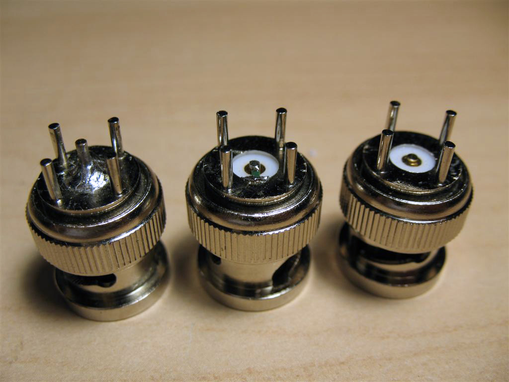 The other two standards - OPEN and SHORT were very easy to make! One should be careful when soldering the SHORT standard not to melt the center insulator with excessive heat (I used a water bath during soldering). On the OPEN standard the center pin must be trimmed down to keep the reference plane the same across all 3 standards.

In order to create RF shielding, provide mechanical protection and facilitate easier handling, I prepared 3 short pieces (~1 cm length) - 2 made with brass tubing (Stock #137, K&S Engineering, 7/16" (11.1mm)) and one of same diameter plastic tube (used for the OPEN standard). I soldered each piece on the inside to the 4 ground pins of the SHORT and LOAD BNCs. Closed-cell foam was used create an endcap for each barrel. The LOAD standard was closed on the back with additional RF shield - tin-plated brass disc, soldered to the inside wall. The body of the OPEN standard was made with the plastic sleeve and glued to the 4 BNC pins - the reason for using plastic is to reduce stray capacitance, caused otherwise by a brass sleeve.
 Final touch - heat-shrink tubing provides color-coding and nice finish.
 This is my full set of (m) BNC calibration standards - in addition to the OSL and LLC standards, I made some extra loads (12.5, 25, 75, 100 and 200 ohms) to aid calibration of other instruments besides the VNA.


19 comments:
>> One should be careful when soldering the SHORT standard not to melt the center insulator with excessive heat (I used a water bath during soldering)
Hi. I'm having trouble visualizing the water bath on this connector while soldering. Can you provide any detail?
The "water bath" was simply a plastic bottle cap filled with water. The connector was submerged in the water to a point that leaves outside only the portion on the back of the connector (where the soldering is taking place). Because the connector has a large thermal mass and on top of it is being cooled by the water, your soldering iron should be adjusted for around 700-730F with a large soldering tip and the soldering procedure shold be perfromed very quickly. The goal is to prevent the heat from traveling down the ground finger contacts and deforming the plastic insulator around the center pin. To aid the soldering process it is a good idea to scrape off with a small file the nickel plating around the inside edge of the barrel (near the back of the center pin) and apply a bit of rosin flux (from a flux pen). Then just quickly fill the gap with solder until it forms a nice fillet.
Thanks.
The water definitely worked to protect the plastic, but I'm still having trouble getting a decent looking solder joint.
I suspect I'm either not waiting long enough (I quit when the water boils), or I don't have enough thermal mass in my iron tip.
I did scratch up the nickel plating before hand and used brush on rosin flux.
I might try borrowing a soldering gun to see if I can apply more heat in less time....
Fortunately I ordered 10 of the connectors so I can sacrifice a few trying to get it right.
As I mentioned before, the key is to use a soldering tip with larger thermal mass (I am using Weller WESD51 with ETB tip), high temperature - 700-730 F and some extra rosin flux besides solder wire core (make sure it does have a rosin core). Speaking of solder wire - I use Kester Sn62/Pb36/Ag2 solder. This solder contains 2% silver (Ag2) and it has a slightly lower melting point (354 F) than the 63/37 (361 F). This is actually my favourite type of solder and you can even get it from Radio Shack (marked as "Silver-Bearing Solder 62/36/2"). Good fillet is usualy indication for a good solder joint but not always! The short calibration standard for the N2PK VNA is only used up to 60 Mhz, so extremly smooth connection is not that critical - you just need to bridge the gap on the back of the BNC connector evenly and close to the surface - stray inductance of the SHORT standard is the critical parameter (as is the stray capacitance for the OPEN). Please refer to the picture of the SHORT standard.
btw. if the water around the connector starts boiling, you are dwelling too long at the joint. I did two SHORTs and in both cases the water just got warm but it never got even close to boiling.
Thanks again.
Had iron set to 730, solder was rosin core (but not siver bearing), plus some brush-on rosin flux. I only had ETA (and smaller) tips (using the analog WES51 station).
I'll pick up ETB and ETC tips (will be handy anyway) and some silver bearing solder and give it another go.
Success!
ETB tip and silver solder made the difference.
Thanks so much for the guidance.
Since I am now running nearly identical O/S/L calibration standards as yours, do you mind sharing what entries you use under myVNA Reference Standards (Cop, Lsh, Lld,Cld, etc)? Are you using the myVNA defaults, zeroing out the strays, or something else?
I know the best would be to have my standards measured on a calibrated VNA, but that isn't likely to happen.
Thanks again.
The short answer is - I am using myVNA defaults. Obviously, the best way is to "characterize" your standards with another calibrated VNA but then you have to have commercial BNC cal standards with known characteristics. You won't be able to avoid the "transfer error" as well. IMHO - too much effort for a small improvment in the accuracy. Remember, the calibration is valid for a specific "reference plane" and if your DUT is not installed exactly at this "reference plane" you'll get error from the interconnects.
I am using one of the Male BNC/PCB mount connectors (the same type I used for calibration standards) as a test fixture for measuring small devices. I trimmed the center pin, (much like in the OPEN standard but I left it just slightly longer for better solderability). Small devices are attached to this connector, placing the device close to where is the OPEN, SHORT and LOAD of the CAL standards. One could get carried away trying to cancel errors and achieve the ultimate accuracy but it all depends on how important is such level of accuracy for the type of measurments this DIY instrument is used for.
Hello Andrey,
thank you for your valuable informations about the construction of coaxial calibration standards.
What capacitance do you use for the OPEN standard definition?
Did you calculate or estimate the fringing capacitance or did you have the opportunity to actually measure it?
Thank you for your assistance
Hello Andrey
Thank you for your excellent article on calibration standards. It has prompted me to write a complementary article about using standard definitions and the link for this is http://chemandy.com/technical-articles/calibration-standards/calibration-standards-article1.htm
Regards William Highton
I am truly flattered if my quick-n-dirty blog notes prompted you write such nice and extensive technical article! Thanks! I've add a link to the article in VNA Calibration Reference Plane post from Sept. 2010
thanks for the feedback. Please take a look at the guys..
Just curious, but was there any reason you went with a single 50Ω resistor instead of four 200Ω resistors? It seems like distributing the resistance completely around the dielectric disc would improve the frequency response (as well as give you an opportunity to hand-pick the resistors to make a closer match to 50Ω), but then again I'm kinda new to this stuff.
Another improvement might be to use a hole punch to punch out a copper disc with a radius that would just cover the dielectric, hammer a small divot in the center, and then solder that onto the connector to make your short standard. This should be better than straight-up solder because pure copper should have less resistance.
Also, wouldn't the open standard be affected by the distance between the center conductor and the far ground plane(and the dielectric between them)? Simply leaving the center pin exposed in the copper cavity seems like it would cause strange resonance at higher frequencies (GHz range).
You have raised some valid points but they are relevant under specific circumstances and parts used.
There are some good reasons why you should go with 4x 200 Ohms resistors as well as a reason why you should not.
4 resistors provide you better mechanical strength - valid if your center pin is not captive. On my connectors the pin is fixed so there is no need for it.
4 resistors give you chance to adjust the overall resistance - the resistor I am using is very precise (better than 0.1% so no need for it). If you don't have VERY accurate DVM you are risking to increase the tolerance as often resistors in the same batch tend to show similar tolerance sign (all positive or all negative)so the error will accumulate if you cant measure the value with high precision (the precision of your DVM must exceed a few times the maximum measured tolerance).
4 resistors will lower the stray inductance - it will be divided by 4. I am using high-frequency resistor optimized to have minimal stray inductance. This type is specifically designed for up to the GHz range.
The disadvantage of 4 resistors is increasing 4 times the stray capacitance. It accumulates and if you are using regular resistors (not high-freq.) it will be increased noticeably.
Also, there is no need for physical distribution of the resistance - what is important for the Load standard is to show pure resistance and no reactance. If there is no reactance, the distribution of resistance in space is irrelevant.
If I had 4x 200 ohms of the same HIGH-FREQ type I currently use, then I might use them but only 50 and 100 ohm resistors of this type were available. Actually, 2 x 100 ohm is a better compromise in my case (at slightly higher price (2x100 vs 1x50))
You can use copper disk in the manner you are describing but it is not going to demonstrate significant improvement if any. The most critical value of the short standard is the stray inductance. The DC resistance is extremely minimal at such short distance and in addition I am using silver solder so this is not a concern at all. Remember that at very high frequencies the "skin effect" is significant - pure copper tends to oxidize on the surface and RF flows only on the surface at very high-frequencies. (That's why high-freq hardware is either gold or silver plated. If you want to use copper disc to bridge a wide gap you should at least tin the surface of the disk.
As for the open standard - stray capacitance is the most important parameter and trimming the dielectic might decrease it - it will also affect the electrical length and the phase error. On the other hand, for a test fixture I am using the same type of connector as the one in the calibration standards. I am not shooting for placing the reference plan inside the VNA connector. I would like to have the reference plane in place where the DUT is located in the text fixture (and there I need some mechanical length in order to able to solder the DUT.
Finally - these particular standards are used for VNA with upper freq. range of 60 MHz only.
Thanks for the detailed explanation!
I recently acquired a 3GHz VNA without calibration standards so I'm looking for something that can do a bit more than 60MHz. For BNC standards I don't need them to be usable and accurate all the way to 3GHz—I'm aiming for around 1.0-1.5GHz.
Just out of curiosity, have you tried characterizing some of the relatively inexpensive BNC terminators which are rated for up to 4GHz like this one? It is supposedly rated for up to 4GHz—which is the practical limit for a BNC connector—but they aren't designed to be calibration standards. I figure that if they are rated for termination up to 4GHz they might make semi-decent standards up to 1GHz.
For that matter, they also have some relatively inexpensive BNC shorting caps on DigiKey. These have the center pin connecting directly to the BNC reference plane, which is the ideal location.
I'm guessing the only problem with using one of these as a short standard is how to come up with a decent open standard at the same reference plane. I thought about buying a BNC cap, drilling out a bit of the center, adding a dielectric of some sort (Ceramic, perhaps?) and attaching the center pin to that. However, securely attaching a center pin to a dielectric at the BNC reference plane sounds difficult and fragile.
have you checked this pagehttp://chemandy.com/technical-articles/calibration-standards/calibration-standards-article1.htm - it will give you some idea about the useability of BNCs as calibration standards for GHz range.
I personally, would not recommend the use of DIY BNC cal standards for VNA measurements above 1 GHz. The fact that a connector is rated for certain "usable" range does not mean that it will be able to serve as calibration standard within this range. Furthermore, the BNCs offer poor connection repeatability during mating cycles at such high frequencies. For HF range VNA, I think they are fine but otherwise price and the ability to quickly connect/disconnect them is just about the only things going on for them.
Also, the rquirements for "termination" are VERY loose compared to calibration standards - the termination you are showing almost certainly is no good as calibration standard - many of these cheap terminations employ nothing more than ceramic-composite resistors or even metal-oxide resitors - I would stay away form such termination loads as VNA calibration standards.
If your VNA is employing BNC ports (which probably means it is very old model) I would just find a good quality BNC to N or BNC-to-SMA between-series adapter and act as the VNA is equipped with Type-N port. And Yes - a good Open BNC standard is tricky to fabricate and you have to account for the exact electrical length of the Open as well. If you are serious about accuracy - try to find a comerical set. IMHO - one can fabricate a good enough (for the lower GHz range) DIY cal standards only if based on SMA. Any other connector type and things get tricky.
I just wanted some BNC standards so that I could more easily test devices with BNC ports. I am totally OK with them being used only for sub-GHz stuff.
My analyzer has N-type connectors and is from 1988. The sngle-port test set that came with it has a APC-7 port for the DUT, which is a but of a pain.
I plan to make a set of SMA standards for higher frequency work. Is it possible to characterize adapters so that the reference plane can be moved when I need different connections?
Again, thanks for indulging me here, it helps quite a bit.
I realize this is a very old thread, but for the benefit of anyone else coming across these excellent instructions, I should just like to add a couple of comments.
1. I have found the board mount BNC sockets on Ebay - they seem to be quite easy to get. I made up the 3 adapters as described added the brass tube and labels - looked fantastic! - then tried them on my DG8SAQ VNWA. I did sweeps of a 400mm test piece of hardline using a Smith chart from 1 to 500Mhz and unfortunately no matter what adjustments I made with calibration kit parameters, delays on the open and short, capacitance of the load etc, the results were poor. Instead of nice concentric circles within the Smith chart, I got wavy traces that went off the screen.
I then had an idea, remove all the brass tubes and try again - voila! beautiful concentric circles and a nice flat S11 dB line. My advice is, leave off the brass tubes and the calibration standards will work a lot better (although they don't look nearly as good!) I believe the one that is particularly sensitive is the Open standard. Adding the tube adds too much capacitative reactance to the infinite impedance.
2. You do not have to worry about the water bath, the sockets are made with teflon which has a higher melting point than the solder. I deliberately tried melting a spare one with the iron, and nothing happened.
Cheers, Peter - VK2AN
Peter - thanks for posting your thoughts on the PTFE PCB-mount BNC connectors on Ebay. I have recently purchased a FA-VA5 antenna analyzer, and am looking to replicate the calibration kit sold by SDR Kits, on the cheap, of course.
The FA-VA5 also uses the SOL method of calibration, like a VNA
de Russ, va3rr
Russ,
Had a look at the FA-VA5 and it looks like great value for money. Let us know how you go.
Cheers,
Peter - VK2AN
Post a Comment