Wednesday, September 9, 2009

N2PK VNA - Power supply PCB and front panel

I received the PCBs for the PS board from the board fab house (Sunstone circuits) and I must say that the fabrication quality is pretty good. The schematics are based on the N2PK/OM3LZ power supply board with very minimal changes on my part. Basicly, there are two voltage regulators: +12V Low-Dropout linear type and +5V switching regulator, LC noise filters for each regulator and two "crowbar" type over-voltage protection circuits combined with over-current and reverse-polarity protection. In other words - the power conditioning is very solid and provides a good protection for the VNA board from a number of potentially dangerous events.
There is an additional +9V regulator circuitry (installed on the bottom of the PS support plate) for the Accessory connector - it is used to power transverters, S-parameter test fixture or the RF-IV sensor.
The PCB layout design was done with Cadsoft Eagle. I started with the OM3LZ board as a reference but at the end I changed the layout a bit. These pictures are of my ver. 1.0 board. The final version of the PS PCB is ver. 2.0 and that one is even more compact and with a smaller footprint. Not sure if the 2.0 board will ever see daylight since I am all set with my PS needs for now.

The PS is done with mixed thru-hole/SMD technology - first the SMDs are installed and then the rest of the components. I added pads for an SMD LED on the +5V line and a current limiting resistor for it. This LED serves as a reminder that the unit is powered when operating with the covers off and it is totally optional to install.


On the bottom side I have a space for an optional LDO 12V linear regulator (Digikey p/n 576-2206-ND (Mircrel MIC29150-12WT)) . This allows for an external power supply with a wide range of voltages - typically filtered DC 13V to 24V. Because of the extremly low drop-out voltage ( 0.35V @ 1.5A) of this chip, the VNA can be powered by a standard 13.8V PS and still be in regulation. For portable use I'll probably power the unit from a 2 x 7.2V Li-Ion battery packs. This regulator can be omitted and bypassed with a jumper but then extra attention needs to be paid to the input voltage in order to prevent the over-voltage protection from triggering (at the price of a blown fuse). There is a couple of extra bypass capacitors associated with this regulator.

Unfortunately, it wasn't cost-effective to put a silk-screen for the SMD components on the bottom but I don't think it is a big issue.

The front panel of the VNA. First step is to drill all holes in the panel. The graphics for the panel are actually a "sandwich" of two layers - printed layer and protective layer. I used Corel Draw to design the graphics layout (any other vector graphics software like Adobe Illustrator will work too). The layout is then printed with a Color Ink Jet printer (printer driver: best quality, transparency) on a sheet of "Avery Clear Full-Sheet Labels" (Avery 8665 or 18665 (better) from OfficeMax/Staples). The aluminum panels must be cleaned, de-greased with alcohol and dry. During application of the printed layer, one should be careful not to smudge the printing or leave fingerprints and must try to prevent any air bubbles from forming at the same time. (I used a piece of the base paper from the label stock (the glossy, waxy side as an "applicator", rubbing the sheet while applying it to the surface). The graphics must be carefully aligned with the holes on the panel during application. Then, the print layer is protected with a second layer of a durable clear self-adhesive plastic sheet - 3M Scotch Laminating Sheets (LS854- 10M or -10G (the last number shows how many in a package, M for Matte, G - for Gloss). After applying the first (printed) layer, compressed air and soft brush were used to remove any dust particles, then applying the protective layer is done the same way - applied slowly while watching out for air pockets . (Remember - it is a "one shot" deal - if something goes wrong during the application of the laminating layer there is no going back - you have to start over with new print layer).

The resulting surface is smooth, dirt and scratch-resistant and because the printed layer is transparent, the front panel has almost the same brushed aluminum/metallic look as the enclosure. Instead of using transparent print layer, a solid-color stock can be used too, but IMHO it looks "flat" and not as attractive as the natural metallic look. Once the two layers were "sandwiched" and pressed well together, I use scalpel blade to carefully cut out the openings and the excess around the edges.

The finished panels came out very nice and professionally looking - practically "commercial product" grade. I am really happy with the results - I think this will be my method for printing front panels from now on.

While looking for a front panel layout solution, I came across an interesting product - Ink Jet printable laptop skin (sold in Office Max). It is a white, self-adhesive vinyl sheet and I think it could be used for front panel labeling as well but I really wanted to preserve the aluminum finish look so I opted for the see-through label sheets. Another possibility is to use one of the products by http://www.texascraft.com/

The front panel is installed on the enclosure along with the BNC connectors and LO jumpers. I decided to color code the connectors because of their number on the front panel. It will be easier to work with the VNA and keep track of all connections.

All of the RF interconnects are done! Initially, I was going to use microwave semi-rigid coax as it provides the best shielding and phase stability but this stuff is too exotic (read: difficult to find/install/work with/using specialized connectors) so I opted for a special mil/aerospace version of the RG-316 by Semflex called SI316. The regular RG-316 is double-shielded with two silver-plated round braids. The SI316 is the same silver/teflon coax but it is triple shielded - it has metalized kapton foil layer between the outer round braid and the inner flat braid. This results in lower attenuation and much better shielding (aprox. 35 db better or >90 dB) than the regular "plain-vanilla" RG316 - the only thing better then this cable would be to use semi-rigid coax (shielding >110 dB).

Next item on the list is the wiring harness and the power supply board mount.

Update: I made a set of bulkhead (f) BNC to (m) SMA internal RF interconnects, using semi-rigid hand-formable RG-405 coax. I left the old SI316 cables for the LO DDS and replaced only the ones connecting both detector inputs and the DDS RF OUT to the front panel. I did not observe any better detector noise figures.

Monday, August 31, 2009

N2PK VNA

Here is the first look of the newly born N2PK Vector Network Analyzer. This weekend I completed the main PCB. It is a ver. 4.3 (dual detector) board. The Power Supply PCB gerber files (layout generated with Cadsoft Eagle) were sent to the board house and I am expecting the new boards any moment. Hopefully there are no mistakes and soon I'll have a power supply ready for the VNA. All of the PS components were ordered together with the VNA'a bill of materials.

The N2PK is a serious SMD soldering exercise - over 300 components on the main PCB and over 700 solder joints. The blank 4.3 PCB was ordered from VE3IVM. All parts are from Digikey. The only additional components were the Valpey Fisher Master Oscillator and the Minicircuits transformers. The VP XO is a very difficult component to find! There is an alternative with Connor-Winfield MO, available from Digikey but I was lucky to find the Valpey Fisher part. I installed all components on one side of the PCB and then moved to the other.

The N2PK VNA is an advanced project - high part count / desnsity on both sides, some fine pitch ICs (not very easy to solder pin-by-pin) and some components in very small packages. Good soldering skills are a must as well as a good set of tools, soldering materials and soldering iron with fine SMD tips (I used Weller WESD51 with ETP / ETH tips). I worked on the board for about 2 weeks spending a couple of hours almost every evening. I could have done it much faster but I was taking my time, double-checking and making sure that there are no mistakes. Troubleshooting is difficult with SMDs and the capacitors are not marked which can cause a lot of headaches should one makes a mistake with the components. My approach was to install all components (small-to-large size order, but starting with the ICs) of the same type/value together, while working on the top side first. After the top side was completed, I did the same thing on the bottom side leaving all connectors for last. I made sure that there is only one type/value components out on the bench at a time to prevent confusion. How well I've done we will see once it is powered up.

I have also prepared custom heatsinks for the MO, DDS and ADC chips. The only thing left to do on the main PCB is the RF shielding cans for both detectors. I need to make screening boxes out of tinplate. After I am done with the power supply / power conditioning board and the wiring harness I'll be able to finally test the VNA.

Sunday, August 9, 2009

"Third hand" aid for SMD soldering

We are continuing with the "Hints and Kinks" category. I recently started working on my N2PK VNA project. Normally, when I do manual soldering of SMT devices I rely on "sticky flux" and tweezers to prepare the components for soldering. First, I'll apply flux solution on the pads using flux pen (like the Kester 186 pen) and then I'll wait a bit, until the solvent evaporates leaving sticky flux residue behind. After applying the flux solution, the right timing is very important for placing the SMD - too soon, while the pads are still very wet and the board will be slippery making it dificult to position the SMD - waiting for too long to dry and it wont be "sticky" enough for the flux residue to hold the component in place. In the next step, using tweezers I'll place and position the component and then press on it gently with the tweezers (small screwdriver, toothpick or even fingernail might work too). The sticky flux residue helps a lot as the component adheres to the board and doesn't move easily or slides across the PCB when I try to hold it in place by applying pressure. Then I'll just tack one (or a few) of the leads, using very little or no additional solder (only what is already on the pads/leads). When the component is secured in place, I'll release the pressure and continue soldering the other lead(s) first. Then, Ill come back with solder to the ones I have just "tacked".
The N2PK VNA project is done entirely with SMDs and because of the sheer amount of components (over 300), I needed some sort of aid for this soldering procedure.
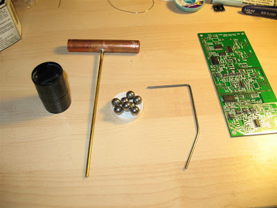
Here is a very simple gadget for SMD soldering which I constructed out of parts laying around on my garage workbench. The Bill Of Materials includes 3.5-4" copper pipe (1/2" diameter, plumbing type), 7" small diameter brass tubing stock (~0.13" OD, ~0.1" ID, usually sold in Hobby stores), 6" steel rod which fits nice and tight in the brass tubing (~0.094" diameter, again from the local Hobby store), some sort of weight (slingshot ammo, lead fishing sinkers, etc) and an empty plastic canister from 35mm film cartridge.

First, I drilled a small hole right in the middle of the 1/2" diameter copper plumbing pipe. I inserted and soldered the brass tubing to the pipe, while making sure that the assembly is a nice straight angle T-shape (because of the large thermal mass of the assembly, I had to use a small propane torch to solder it). The piece of steel rod should be formed into the shape shown on the picture above. Next, I drilled a small hole in the bottom of the film canister and another one in the plastic cap. The holes need to be a tad smaller than the brass tubing's OD so the tubing fits in very tight (with significant friction). I inserted the brass tubing through the plastic canister and the cap, filled the canister with weight (it could be anything small and heavy - nuts, bolts, lead fishing weight, marbles or slingshot ammo (as in my case)). Than, I inserted the end of the steel rod into the brass tubing.

Done!

This simple 15 minutes project will give you a great "third hand" for SMD soldering. The cool thing about it is that it is very easy to control the amount of downward pressure on the components - just slide the film canister up or down on the brass rod for fine control or open it and add / remove weight for coarse. Also, the film canister could serve as a solder dispenser - it can hold a small spool of solder wire which can be pulled through another small hole in the cap. Yet another possibility is to house inside the film canister a couple of 3V lithium batteries, on-off switch can be installed on the plastic cap and connnected to a White LED at the end of stiff insulated wires.This can server as "goose-neck" type of miniature work light, illuminating the immediate area of soldering. Small magnet could be glued to the canister to keep handy small parts and components. Even a small magnifying glass can be attached somewhere - what other features can be added is limited just by your imagination.

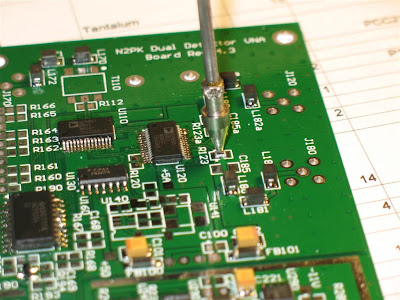
The soldering weight is pressing onto chip, ready to be soldered. If the steel rod rotates too easy inside the brass tubing, glue can be used to fix it in a straight vertical position.

This gadget has a small footprint on the workbench and it can be used with almost any size boards. It can be used inside larger equipment enclosures without the need for removing the circuit boards.

In addition, special tips could be fabricated for the end of the rod and used with different shape and size components. The tip in the picture was made out of an old food thermometer probe - something I just had in one of my junk boxes.


The very tip was shaped to have a flat face. This picture shows a 0805 SMD resistor ready for soldering. One added benefit is that the metal (nickel-plated copper) tip works as a miniature heatsink for the component being soldered, reducing the chance of overheating and thermal damage.

Wednesday, August 5, 2009

Palstar AT2K - 160m Mode Indicator Mod

The AT2K is probably one of the best tuners I've ever used but as we all know - "nothing is perfect" and this tuner is not excluded from the above-mentioned statement. It has one somewhat annoying flaw - it lacks a good indication when the extra inductor is switched in circuit for 160m band operation. As a result from it, every now and then I'll forget that I have had the 160m switched on and I'll try in vain to find a match for my dipole antenna on the higher bands. The only indication on the front panel that 160m mode is selected is the button itself but this is not very obvious (especially in a dark shack) so I decided to add an LED indicator.
This is an extremely simple and quick modification - nothing special but it improves the tuner's ergonomics IMHO.

The LED is connected to the coils of the relay responsible for switching the 160m inductor in series with the main roller inductor. Current limiting for the LED is done with a 1.8 kOhm - 2.2 kOhm resistor. The LED can also be connected straight to the 160m switch board but it is very hard to get to the board with a soldering iron without removing the top peak-hold/switch board.

The key component for the mod is a 3 mm LED in a small yet elegant black bezel - Digikey P/N 67-1192-ND. It looks excellent on the black front panel just above the 160m button. This LED bezel assembly requires a 4.1 - 4.3 mm hole. One needs to make sure that all of the metal particles from the drilling are completely removed from the enclosure!

Maintenance tip: I noticed that the roller shaft was very dry and needed lubrication. I applied very small amount of conductive grease using a fine brush. The grease needs to be brushed as a very thin film just on the shaft. (!) One must be very careful not to get any grease on the roller itself or the inductuor's coil as this might cause huge arcing problems. The tuner normally comes with factory applied conductive grease but on my unit it wasn't enough. I moved the roller up and down the shaft a few times to evenly spread the grease while making sure there is no excess that can fall onto the inductor.

For DIY conductive grease : I used some white lithium grease (sold as Genie Screw Drive Garage Door Opener GLU-3 lubricant - this grease doesn't gum up easily) and added a good amount of fine graphite powder (I used a fine file (! not sandpaper) and soft carpenter's pencil to produce the powder). I mixed it well, while adding more graphite powder until the mixture thickened a bit.

2010 Update: Palstar changed the design a bit for their current version of AT2K. They no longer are using the 18 uH inductor which had to be padded with extra 10uH inductor for the 160m band. The new inductor is 28 uH therefore there is no longer need for a relay and switch in order to add extra inductivity and tune 160m so this mod is irrelevant.

Friday, June 5, 2009

"Fancy" Bird 43 Dummy Element

This year at Dayton, as the flea market was concluding on Sunday and I was hunting for last-minute bargains, I came across a few non-functional Bird 43 slugs in one of those "Everything $1" bins.
My first thought - I'll repair them. As it turned out, they were for frequency/power range I had no interest whatsoever. So what one can do with a damaged Bird 43 slugs besides repair? A few things actually - it makes nice dummy slug for the Thruline section, it can be reworked into a RF sampler or just keep them for parts.
The original aluminum dummy slug could actually be improved on - it has a small design flaw IMHO - when inserted, it keeps the contact finger of the Thruline section pressed and under tension. This might lead to metal fatigue and eventually the contact finger could loose its spring action, causing poor electrical connection with the slug. Once, I saw a third party "dummy slug" where this issue was addressed with a shallow groove allowing the contact finger to rest. The normal Bird element already has two small lateral indentations on each side where the contact points are protruding.
First I "gutted" the slug, completely disassembling it and removing everything from inside including the internal contact plate. This was simple enough and left room for the contact finger of the Thruline section to rest without pressing onto anything. But why stop there? How about a hygroscopic dummy slug to absorb trapped moisture inside and to keep the Thruline cavity nice and dry?

I sealed the two contact point holes of the slug with copper/kapton tape from the inside. Then I made 6 small holes on the bottom of the white Teflon cover (which normally protects the coupling circuit).

I placed a piece of the material used to make the little bags with Silica gel on the bottom of the cover, over the holes and then filled the element housing and the Teflon cover with Silica-gel beads. The piece of "silica-gel bag" material serves to stop any Silica-gel beads from going through the holes, while allowing air to flow in and out of the slug. (tea-bag material could also be used)

I reinstalled the Teflon cover on the slug, pressing it until it snapped into place.
Silica-gel is very easy to find - people normally discard the Silica-gel bags after they buy a pair of new leather shoes or a hard drive - I collect the little Silica-gel bags in a jar and re-use them.
Re-cycling Silica-gel is also easy - the Silica-gel needs to be "baked" for about 2 hrs in a toaster oven on "high" (250 - 300 F). This process will evaporate the moisture absorbed by the beads and the batch will be as good as new, ready to absorb more moisture again after it cools down.

The new dummy slug is lighter, preserves the contact finger of the Thruline section, absorbs moisture and keeps the cavity dry and most importantly - makes a cool rattle sound when you shake it :-) Not bad for $1.
Update: Another idea for enhancing the functionality of the "dummy slug" even further - small piece of felt/cloth/foam can be attached inside each contact bed of the slug. Then, (optional) a drop of Deoxit D5 solution can be used to moist this "cleaning pad". Each time when the slug is inserted or removed, it will wipe clean the contact finger.
In addition, instead of using only silica-gel beads, the dummy slug could be filled with a mixture of silica-gel and activated carbon. (another option, if moisture is not an issue, is to replace the silica-gel entirely with activated carbon). The activated carbon will absorb any sulfuric gasses in the air (like hydrogen sulfide) - sulfur is the main cause for the black tarnish on silver/silver-plated surfaces (the Truline cavity is silver-plated).

Thursday, May 7, 2009

SB-200 - correcting the filament voltage

Most of the SB-200 amplifiers (including mine) suffer from "high filament voltage". One theory I've heard is that when the amplifier was designed in the 60s, the power transformer was calculated for AC mains of 110V/220V and today we are using 120V/240V AC. While a bit higher plate voltage is welcomed , higher filament voltage is a bad thing! According to an EIMAC study: " A 3% increase in filament voltage above the maximum rating will result in a 50% decrease in tube life."
The factory specification for 572B heater voltage is 6.3V +/- 0.3V @ 4A. My calibrated (NIST traceable) DVM measured 6.65V AC (True RMS) for the filament voltage @ 240V AC mains. This reading is beyond the maximum allowed and it should be corrected!
I decided to bring the voltage down, just slightly less than the recommended 6.3V.
The increase in the filament voltage is of no benefit to the output of the valve. 572B is performing at full output with even less than 6.0V filament voltage! My target voltage was 6.25V - about 0.4V down. A thing to note is that the voltage of my 240V AC line does not fluctuate a lot over time - just a couple of volts. Using resistors to correct the filament voltage is the obvious solution except sometimes it is hard to find the right ones for the job! Each amplifier will require custom values for the resistors (determined by the individual transformer and maximum AC line voltage).
To drop the voltage across a resistor by 0.4V (in my case) while drawing 8A of current (2 x 4A for each valve) results in calculated total resistance of 0.05 Ohms. To complicate the matter further, this resistor should be capable of dissipating at least 4W. To preserve the circuit symmetry (the filament secondary is center tapped) I decided to use 2x 0.025 Ohms /2 W resistors - one for each side of the secondary.
Precision current-sensing power resistors could be one possibility. Another solution would be to use a coil of small gauge Teflon insulated wire - AWG #22 for instance. The small gauge will cause the wire to heat up increasing the resistance and corresponding voltage drop. (Even better - coiled on a ferrite rod, thus creating a second filament choke - more inductance equals better choking in this case). I might actually try this someday but there is not much space in the tube's socket compartment and I want this to look neat.
Instead, I made DIY resistors out of Nichrome-60 AWG #22 wire (0.65 mm), left over from my Low-Q VHF suppressors kit. This wire has very high electrical and thermal resistance. To reduce the heating and thermal stress on the short piece of wire required for each 0.025 Ohm resistor (I am using two of them in series for 0.05 ohm total resistance), I actually made each resistor out of two paralleled 0.05 Ohm "resistors".
Recap - i need a 0.05 ohm resistor but for circuit symmetry, I'll use 2 x 0.025 ohm in series (one on each end of the filament winding, just before the filament choke). To increase the power rating of each 0.025 ohm resistor on the other hand, I'll be using 2 x 0.05 resistors in parallel to form the actual resistor.

I used a little over 3cm length of Nichrome wire, bended into a "U" shape. Both ends of the wire are soldered together, creating small elongated loop. The solder points for the resistor are at each side of the elongated loop. This way, each 1.5 cm length of the wire would have to dissipate about 1W for a combined power rating of 2W per resistor.

I inserted each leg of the U-shape wire into Teflon tubing before soldering them together, forming the "resistor". This will prevent an "internal short" in the "resistor". My LCR meter shows exactly 0.025 Ohm.

Each 0.025 Ohm/2W resistor was placed in-line with the filament secondary, just before the filament choke. For soldering the Nichrome wire I used the instructions, flux (corrosive!!!) and silver solder supplied with the suppressor kit. The solder is a tin-silver alloy with high melting point and it should be used also for soldering the "DIY resistors" to the filament choke terminal strip and to the transformer leads. The heat produced by the resistors is substantial - I barley can keep my finger on the resistor (right after I shut the amplifier off (!)), so high temperature solder is needed in order to prevent the joints from failing over time. The result is as expected - filament voltage now measures exactly 6.25V @ 240V AC Mains!

I was ordering parts from Mouser for another project so I ordered a few high-power current sense resistors. Here is a more "commercial" modifications for those who don't feel like making their own resistors. The end result is the same as it is with the DIY resistors. I have the feeling that the commercial resistors heat up a bit less (obviously, larger surface area - better cooling) than the nichrome wire but it is hard to tell just by touching them with my finger.

Monday, April 20, 2009

Common-Mode Current Choke (Ver 2)

There are two major changes in Version 2! The first change is purely a mechanical one- no enclosure anymore - the choke is not as compact as it is in the original design (Ver 1). It is not a "one-box" device but rather an in-line jumper-like device. Before, the enclosure was keeping the coaxial from damage by garden critters and the brittle ferrite rings from mechanical damage. Now, with the open design, one should be more careful while handling/installing the choke. On the bright side - there is one less M/F Type-N connector pair (less insertion loss and one less connection to waterproof) - now the balun has one Male and one Female connector on each side, oppose to the two female bulk-head connectors mounted on the box. Because the antenna side pigtail (/w Male Type-N connector) is longer, there is no need for the short Male-to-Male jumper to the antenna. There are only two connections to waterproof. The open construction also allows for better cooling during Legal Limit power levels.

The second change is electrical - since the space is not limited anymore, now the choke has more ferrite rings (24 pcs vs 18 in the old one) and less coaxial cable turns (2.5 turns in the new version vs 3.5 turns in the old) through the binocular core. This improves the upper frequency impedance (speaking of which, I have a couple more mix 43 single turn ferrite beads on the coax pigtails, for a total of 3)!  More ferrite rings in the core - more inductance (to make up for the lower number of turns). Less turns on the other hand means a decreased capacitive coupling between the turns on higher frequencies. My MFJ-259B is limited in measuring the complex impedance (Z) up to 650 Ohms. The choke was measuring >650 Ohms up to about 20 Mhz. The impedance is around 400-500 Ohms at 30 MHz, mainly due to the capacitive coupling between the turns. I have installed an additional plastic "jacket" over the coaxial in attempt to increase the space/dielectric between the turns and decrease the capacitive coupling but can't really tell if this has any real effect! I am using the same LMR-240 coaxial (RG-8X type with a solid center conductor). The choke should handle well power levels up to 1.5 kW but I am not planing to use it with more than 1 - 1.1 kW anyway (ACOM 1000 amplifier).
For steady 1.5 kW use or with antennas, exhibiting very high SWR, I'll recommend the use of high-temp cable such as RG-142 (silver/teflon) for the balun. This cable has a solid teflon center insulator and there is no danger for the center conductor to migrate to the shield and short it, if substantial heating occurs - something that is possible with the polyethylene-foam based center insulator of the RG-8X / LMR-240.
The ferrite toroids  I used are made by FairRite (Part# 2643801002) - mix 43, OD 28.5mm, ID 18.5 mm, H 7.5mm. Price is about $6.10 for 10 pcs - Mouser Part #: 623-2643801002.

The new Common-Mode Current Choke takes a little more linear space but this is not a big deal. I am planing to put extra mechanical support (another plastic stake) for the choke itself.
Update: I tested the current balun with my VNA and here are some plots:

Insertion loss on HF <0.1 dB (due to connectors and coax cable insertion loss).

Complex impedance (Z) for Common-Mode current is 2200 - 2500 Ohms on the 80m -40m bands and drops down to ~300 Ohms on 6 meters (just as expected). On the 20m band chocking is still > 1kOhm.
Overall, for a current balun of this size and cost, the result is excellent and it completely serves the purpose. I wanted to have it primarily for the lower bands - 80m and 40m but get some good values on 20m as well. If mix #31 is used for the ferrite,  the optimization will be even better in the lower HF spectrum.
2-3 kOhm Chocking impedance is completely adequate for a tunable antenna like BigIR where the SWR never exceed 2:1 (given that the number of radials is sufficient and they are properly sized). I actually get SWR of 1.1:1 to 1.2:1 on 80 meters.
The VNA test just gives me a nice confirmation that I have achieved my design goal when building the choke.
If more chocking impedance is needed, more of these in series can be built on the same piece of coax and folded to save linear space.

A transmission scan shows attenuation >30 dB on the lower bands but this is a less relevant test to a real-world application as the measurement of attenuation is done in a true 50 ohm system. In reality, the antenna feedpoint (Z) is never exactly 50 ohms.

Sunday, April 12, 2009

Common-Mode Current Choke Disaster!

It is Spirng time and Spring means rain - lots of rain! Yesterday I wanted to use my SteppIR vertical antenna after a couple of months rest (I've been using my dipoles meanwhile). When I did, the SWR was very high on all bands regardless of the SteppIR tuning. It was 4.3:1 even when the element was completely retracted and the same thing with completely extended element - 40/80 meters tuning - a sure sign of trouble. No matter what I was doing the SWR was not changing and very strong signals were extremely attenuated - about 1/3 of what the dipole was receiving! MFJ-259B was showing the same thing - the impedance was changing a bit on different bands but the SWR stayed very high. Next thing to try was the DVM - aha!!! - DC resistance between ground and antenna was 6-7 kOhm and constantly changing up and down (ideally it should be just a few ohms of DC feedline resistance as the 80m coil has a built-in balun showing as 0 ohm for DC)! After going to the antenna site, everything looked normal until I started the troubleshooting by inspecting first the common-mode current choke/balun in the base of the antenna!
Here is what I have found upon removing the cover of the balun enclosure! Totally flooded - just missing a few toads inside! Not only that! Note the left antenna connector, between the two top screws of the flange connector, where the coaxial is soldered to the center pin receptacle of the female N connector - the pin receptacle, together with the white dielectric insulator (visible between the bolts) were (!) pulled out of the N connector housing and were almost entirely inside the enclosure! As a matter of fact - they were so far out of the connector's barrel - the center pin of the male antenna connector was not making contact - not even close! The solder connection of the coaxial shield was broken off too! I have no idea what happened there but looks like some serious force was in play - I can't do such a thing with my fingers and even with a tool will be a chore! One speculation is ice. In a solid block of ice this might be possible during freezing / melting cycles during the winter but none of  the ferrite toroids were broken! Another possibility is a miniature steam explosion. When I used the antenna last time, was with 1kW according to my logbook, water inside the tightly coupled male-female N connectors could have vaporized and the resulting steam could have pushed out the dielectric inside the box and ripped off the shield's solder joint- the middle insulator is the only part that can easily relief such pressure. Who knows... Bottom line - the whole balun is badly damaged and I'll be making Version 2 once the parts arrive!
The reason for this disaster is very simple - having too much faith in labels such as "Weather resistant electrical box" (aka the balun enclosure) from Home Depot. By "Weather resistant" they actually mean - "water resistant", forgetting that Sun exposure is part of the "Weather". The seal around the cover failed. It is a ring type gasket and either the gasket material changed over time or it was no good in first place. After removing the gasket, the seemingly dry gasket produced a lot of water just by squeezing it with my fingers. Seems to me that the gasket is made of some sort rubberized open-cell foam material (?!? huh?) and it was SOAKED with water. It is possible that the UV exposure broke down the rubberized coating and changed the properties of the material - the gasket no longer functioned as gasket but as a wick letting water to fill the box.
Looks like Carlon - the manufacturer of the so-called "Weather Resistant Electrical Box" needs to learn more about gaskets and materials or revise the description. (Needles to say - the cover was screwed very tightly so the only thing really to blame is the gasket!). There was also a very small discoloration and deformation of the cover (due to the sun exposure) but that was well within the tolerance of the gasket. I should have removed the original gasket when I built this choke and use some silicon sealant instead but back then I didn't even think they will sell electrical boxes with such poor choice of gasket material - now I know - they do! Lesson learned!
Construction notes for the original choke (Ver. 1.0) are on my antenna site. Before the damage, the choke worked just great! The new one, I am planing to build will be of open type design, with no enclosure.
If anyone decides to built this version - my recommendation is to have a small drain hole on the bottom or use a bead of black RTV sealant around the edge of the gasket, once the box is closed to protect the material from UV damage.

Thursday, April 2, 2009

Hamshack RF Signal Path Diagram

I've updated the diagram to reflect the latest changes in the RF paths / equipment. The main change is the way the output power is measured. In the new configuration I am using one watt-meter for output-to-antenna power and another watt-meter for the output-to-dummy load power. In the old configuration, each amplifier had its own dedicated watt-meter for the output. In addition, the main high-power dummy load is now an oil-filled Bird 8201.

Monday, March 30, 2009

Coaxial Switches

I've been looking for a good coaxial switch for quite some time! I went through the "usual suspects" - MFJ, Daiwa, Diamond and Alpha-Delta. The quality of execution varies from pure junk (MFJ) to very good (Diamond and Alpha-Delta).

Alpha-Delta 2 and Diamond CX-210.

When it comes to internal design and construction, all of these switches share common design concept (especially the A/B (SPDT) type) - a moveable contact "finger" engaged by the lever and a couple of contact points in the same cavity. They are not "true coaxial switches" and in my book they are far from "great"! This design is just a notch better than an "open frame relay" type A/B switch. There are problems with poor port-to-port isolation, insertion loss, SWR, frequency response, reliability and power handling, etc - all common problems for many "ham grade" (read "inexpensive") coax switches.
I was on a quest for a great coax switch and I finally found it - the Transco M1460 series switches.

Transco M1460-30 double pole manual transfer switch.

Transco was a US company, manufacturing high-end RF switches and relays many years ago. Their line of switches was acquired by DowKey and the manual type of the M1460 series was discontinued.

It looks to me that when it comes to RF switches it is the classic case of "they don't make them like they used to"! Truth be told - the Transco switches are not your average "ham grade" type - these are very high quality commercial / military RF switches with the price tag of hundreds of dollars in their time. The good news is that now they can be found sometimes at hamfests or eBay for anywhere from $10 to $50. These unassuming, old switches have incredibly clever yet simple internal mechanics and were manufactured with extreme precision and tight tolerances for the US Army, Navy, aviation, etc. (some of them are labeled as "US Property"). There are a couple of types - manual and motorized type, each in different configurations, port number (and voltages for the electric type). At 10 MHz, typical isolation is >80 dB (the actual is close to 100dB), VSWR 1.05 and Insertion Loss 0.05 dB. Some switches are rated for use at up to 10 GHz with maximum power of 300W CW at 3 GHz! On the HF frequencies, this translates to more than 1.5 kW (in practice it is only limited by the N type connector power ratings).
I managed to acquire a couple of M1460-30 (Double-pole transfer switch) and M1460-4 (4 position switch) for the price of a single Diamond or Alpha-Delta STDP switch!
M1460-4 (or 5-6) is a straight-forward 4(5,6) position switch designed to connect single port to 1-4(6) ports.

M1460-30 transfer switch can be used as an A/B switch as well but it is really handy as a transfer switch - I am using it to connect my two amplifiers to one of the antennas and a dummy load. With this switch I am able to swap the amplifiers to different ports and decide which one is connected to the antenna while the other is connected to the dummy load. It can be used also to swap 2 antennas to 2 transceivers or as by-pass/in-line switching of amplifier, preamp, pre-selector, filter or antenna tuner. It is very versatile type of switch around the ham-shack.

These Transco switches are good up to the GHz range and are using silver-plated N-type female connectors with teflon dielectric.

At the back side (internal, pictured on the right) of the N connectors there are (4) contact points with spring-loaded pins. The internal switching assembly (picture, left) contains two contact "bridges" (true coaxial lines) with 2 silver plated contact points (each) in constant-impedance channels (teflon dielectric). When the switch is rotated, two ball-bearings located at 180 degrees from each other (left, center) are pressing against a special action disc with 4 (at 90 degrees) radial groves (right, center). In the center of this disk there is a sleeve bearing for the shaft. The groves are with beveled edge to facilitate easy sliding in/out of the ball bearings. Normally, the ball bearings are resting in the radial groves, but during rotation of the switch they come out of the groves and press against the raised part of the disc, pushing back the whole switching assembly on its axis and away from the static contacts. In other words, the radial movement is converted into axial movement.

There are 6 springs in the coax bridge assembly creating an opposing force in the axial direction (located on the front side of the bridge assembly around the switch shaft and pressing onto a special graphite covered friction plate). The axial play causes the whole assembly to retract away from the contact points plane and allows for a clean rotation. When the rotation is completed and it comes to a stop at the next switch position, the steel balls are pushed back into the next set radial groves. The "bridge" assembly is pushed on its axis by the springs, flush against the contact surface (back plate) and the contact bridges in the assembly push against the N-connectors contact pins (also spring-loaded) and close the circuits. The back face of the switch assembly is pressed against the back-plate, grounding the assembly. As a result from this design feature, both contact pairs are completely sealed/shielded from each other creating very high port isolation. The SWR is extremely low and there is no impedance bump because of the constant 50 ohm impedance cavity of the contact channels. The actual contact points are silver plated and with large contact areas allowing for high power use. Very good electrical contact is established by the large, polished, flat faces of the contact points and internal springs in the N-connector portion, pressing the pins against the corresponding contacts in the bridge assembly.
There is a loud "clank" when the switch is completed and in the next position, but the rotation is nice and very smooth. The switching knob slightly moves out on its axis (about a 1/8 inch) at the beginning of the switch cycle and retracts back at the end of the cycle. Its all automatic, not like in Bird 74 where the operator must manually pull the lever out, rotate and then push it back at the end of the rotation.
The only "drawback" of this design (if I can even call it "drawback") is the relatively high force need to operate the switch - it feels a bit "heavy" at the very beginning of the rotation. A large (easy to handle) knob or lever is needed to actuate the switch with less effort.
There are 4 screws on the front of the switch used to attach a "face plate" with labels for the positions. Two screws on the side of the switch are used for mounting.

M1460-4 is a more complex design but very similar. Instead of a sleeve bearing in the center of the static contact back-plate with the N-connectors, there is a special silver-plated coaxial two-part contact arrangement. Also, the grooved plate and the steel ball-bearings are reversed in place - the plate is located on the switch rotor and the ball bearings are on the static back-plate. There are more springs (8) and the pressure plate (friction surface) located on the back, around the shaft is larger.

The motorized version is comprised of two parts - RF Head and Actuator. The Actuator is driven by an AC or DC motor, and includes a "gear box" speed reducer and a rotary switch which disconnects the motor once the switch is in the next position. The RF Head could be separated from the actuator and used as a manual switch if needed. The separation is not that difficult but a proper lever needs to be used for manual actuation since the shaft of the RF head is shorter than the standard manual version.

For maintenance, I cleaned and lubricated the contacts with Deoxit D5 solution and treated them with Deoxit ProGold. I removed the old grease and lubricated the pressure plate, both sleeve bearings and the action ball bearings with white lithium grease. I also removed the tarnish from the silver plated N-connectors with a product called Tarn-X.

Transco switches are clearly the best RF switches I've seen so far and IMHO are better than the famous Bird 74 switch. I replaced all of the RF switches in my shack with Transco getting excellent results!

Thursday, February 26, 2009

M3 Electronix LCR Meter

The LCR Meter by M-Cubed Electronics is another very nice kit - IMHO - a must for every workbench. The kit is using very high quality components and PCBs. Included is a powder-coated aluminum case which gives the LCR Meter very professional look. This LCR Meter by itself has an enormous amount of features (all listed on their web site). There are also a few optional test fixtures available. The accuracy is impressive for a kit - basic accuracy of 0.2% using the supplied calibration resistors. The best part is the use of the "4-wire test method" which eliminates errors caused by the test leads and fixtures - a feature normally seen only in high-end test equipment. Upgrades of the firmware are done by sending the unit back to M-Cubed. There is a JTAG connector on the main PCB which allows for re-programing of the PIC but the firmware code is not made public. All SMD components (incl. the PIC) were pre-installed on the PCB along side with some other components, needed for the initial programing of the PIC (crystal oscilator, a few caps and the JTAG connector). The rest of the components were sorted by type in plastic bags. The assembly instructions are very clear and logical. The only gripe that I have is about the capacitors - some of them are small and on the top of this, some of the value markings were partially erased. Even with the help of my Zeiss-Winkel microscope I was unable to identify some of the caps just by looking at them. I had to use another LC meter to actually measure their values - this is not a problem if you have a LC meter handy but the irony is still there - you need a LC meter to build LC meter. Another small issue is the power connector - a male 5.5mm x 2.1mm barrel connector is not provided with the kit and you have to find one - I rather pay a little extra and get it with the kit instead of wasting time to look for the proper connector. Other than that, the assembly went very smooth over a couple of evenings.

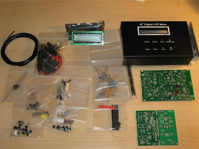
This is the content of the kit right out the box. Calibration resistors are also provided with the kit. The basic kit comes with a probe made out of 4 Pomona-style clips - everything need to construct the probe is supplied with the kit.

These are the 4 boards - Input board, Keyboard board, Main PCB and LCD. Most of the resistors supplied with the kit are of the 1% tolerance type but there are also some 5%. I had plenty of 1% resistors in stock so I replaced pretty much all of the 5% resistors. This might not improve the accuracy a lot but at least the 1% (blue body) are metal-film type resistor with more stable values than 5% carbon-film type. The specified accuracy for the meter is between 0.2% and 0.8% when calibrated with the supplied 0.1% calibration resistors.

The PCBs are "sandwiched" together (using connectors and stand-offs) in the aluminum enclosure. 5-pin DIN connector (on the right) is used to connect the test probe or fixture. On-off switch and the power connector are wired on the left side. Very little space is wasted inside the enclosure and the PCBs are densely populated as well.

This is the finished meter. This meter is using the 4-wire probe method for measuring DUT (Device Under Test). 2 wires are supplying and measuring the AC (0.5Vrms) current thru the DUT and 2 other wires are measuring the voltage across the DUT. This allows for a very accurate measurement canceling out the error introduced by the probe. Furthermore, I increased the accuracy by calibrating the meter with my own 0.01% resistors instead of using the supplied 0.1% calibration kit. If an accurate Ohm-meter is available, the firmware allows for correction of the calibration values and then the supplied resistors can be used just as a "transfer" standard. On this picture high-current 270 uH inductor reads 263.8 uH.

During measurement, the display shows additional information such as the test frequency used for measurement (adjustable up to 15.6 kHz), the Auto-range mode, currently used range, test model (parallel or series), secondary value (ESR in this case) etc. Capacitor with marked value of 5.6 pF and tolerance 5% reads 5.56 pF. There is a menu option for the averaging mode - higher averaging results in more stable measured value. The test frequency is very low - only up to 15.6 kHz (there is an EU version with max freq. of 25 kHz) - not really RF range measurments but gives an idea.

The power supply for the meter should be between 9V-13V. Current draw is about 200 mA . Using the small 9V alkaline battery is out of question - it will last just a few minutes. The backlight can be switch off but the current is still too high for such battery. I am using 2.9Ah 12V SLA battery to power the meter.

This picture shows the inductance and Q for 330uH inductor in "series" model (Ls).


I built a few different sets of probes - Kelvin clips, 4-wire Pomona-style clips and SMD tweezers.
The Kelvin clips probe is the best all-around type. One half of each clip carries the Drive and the other half the Sense signal. It has the best accuracy for testing leaded components. The 4-wire clips probe is useful for testing transformers (there is a special mode for this), already installed components or using it with a small PCB fixture for quickly checking / sorting multiple components (there is a SORT mode alowing a tolerance value to be set and and audio beep indicating if the tested component is conforming or not). The SMD tweezers are a bit less accurate when measuring capacitors due to stray capacitance in the actual tweezers.

Tuesday, February 10, 2009

M3 Electronix Semiconductor Analyzer

A little known company called M-Cubed Electronix is selling an excellent little kit - PIC based Semiconductor Analyzer. It is one of those "I don't know how I managed without it?" things. On their web page - http://www.m3electronix.com/ there is a plenty of information about the features of this Analyzer - it fills a whole page so I am not going to relist them. From hardware point of view there is nothing special - just a PIC, LCD, 3 analog multiplexers and an array of precision resistors. used to set different measurment ranges. What is amazing is the firmware inside the PIC - the Analyzer is using mathematical models of semiconductor devices to detect the DUT (Device Under Test) and measure its parametters accordingly. I must say that this little Analyzer has an impressive accuracy and set of features and it is "a must" for every electronics workbench.

All components are high quality - no surplus stuff. Components are sorted by type. The plastic enclosure (sold separetly) is somewhat bulky anc could be better but it works. Assembly instructions and user manual are in digital form (CD).

Here is the complete PCB and Display Board. On this picture, the PIC is not istalled yet in it's socket. Upgrades to the software are free when available (requires shipping of the old PIC back to the company or buying a new PIC with the upgraded firmware)

The finished analyzer. Device Under Test is an ancient Bulgarian-made Germanium Transistor (GT2 306). There is no specific order to connect the test clips - the analyzer will automatically detect and display the DUT pinout. Every 5 seconds the display changes, scrolling thru a few data screens and showing various test results. After 30 seconds the LCD backlight is switched off to conserve power.

Here is another data screen. Diodes are connected only between the left and right test clips. The feature, detecting internal short (fault condition) in components can be used as ohm-meter for up to 50 ohms.

One small modification I have done is to drill a hole to the right of the LCD and glue a micro-switch connected to the calibration jumper. This allows me to perform calibration without opening the eclosure. I might drill another small hole for access to the trim-pot controlling the display contrast.

Thursday, February 5, 2009

Palstar AT2K

Palstar makes some of the best antenna tuners out there! Last year after much research I got their AT2K model. The build quality is simply amazing. This tuner almost tunes my standard G5RV on 160 meters. It also work on 6 meters due to the smaller roller inductor. The built-in Peak-reading watt/SWR cross-needle meter works really well and with very good accuracy.

Internal picture of AT2k. Most components are manufactured in-house by Palstar, including both variable capacitors and the roller inductor. The quality of the components is impressive - everything is very solid and heavy duty - indeed "built like a tank". All solder joints are perfect.

Roller inductor, 160m inductor (toroid) and switch-in relay. The high-power balun transformer (toroid) is visible at top-right.

Load and tune high-voltage variable capacitors - top-left is the power/SWR detector, top-right is the PCB of the peak-and-hold circuit. At bottom-left is visible the ceramic rotary RF switch.

Palstar AT2K and Heathkit SB-200 in my shack. AT2K looks stylish and it is very easy to operate! The two vernier dials allow for very fine tuning.

2010 Update: The current version of AT2K was changed from the original design. As a cost-saving measure, the internal 4:1 balun (used with balanced antennas) was removed from the tuner and it is now sold separately as an external option. Another change is in the inductor - the original inductor was 18 uH and was padded with extra 10 uH inductor for 160m only. The new inductor is 28 uH, eliminating the extra inductor, relay and switch at the expense of the tuning resolution.

Wednesday, February 4, 2009

"Gettering" GU74b / 4CX800A

There is no such thing as a perfect seal! Vacuum tubes (especially high-power transmitting tubes) not used for a few years might exhibit serious problems if put into service without a prior conditioning of the vacuum. With time, gas molecules leak inside and/or are released by the tube's internal components. With years and years of storage, the vacuum could deteriorate to a dangerous level and once the tube is used for the first time it could "flash-over" - the gas molecules inside will become ionized by the electron flow and this will create a flash of high-temperature plasma between the cathode and anode, damaging the grid(s) and other internal components. A chemical composition, called "getter" is factory deposited inside the tube to complete and maintain the quality of the vacuum (the getter is visible as the shiny, black-metallic area on the inside wall of the glass envelope (in smaller tubes)). In power tubes, the activation of the getter is done by heat. Therefore, it is recommended, before putting into service a power tube with very long on-the-shelf life (more than a couple of years) to condition the vacuum first. This is done by applying power to the filament (cathode heater) only and leaving it on for a period of time. The hot filament will heat up the getter and also will improve the vacuum by itself (gas molecules will react with the hot tungsten filament and the cathode surface, forming chemical bonds and effectively extracting them).

Here is a simple fixture I used to "getter" my newly acquired GU-74b tubes (NOS, manufactured in 1990-92).

The "chimney" is made by cutting the top portion of a plastic soda bottle ("Classic Seltzer Water" sold at Costco to be more specific :). The cooling fan is from computer power supply. The tube MUST (!) be cooled with forced air while being "gettered" or the high temperature will damage the metal-ceramic seals and destroy the tube. The fan is raised about an inch from the surface to allow for air intake. I slowly raised the filament voltage from 3v to 12.5V (12.6 is the nominal voltage) over a period of 5 hours in 5 steps (3v, 5v, 7.5v, 10v, 12.5v) using variable power supply. I, then left the tube running with the nominal filament voltage for about another 8 hours. The fan should run continuously, powered by a separate 12V supply. The current drawn by the heater is around 3.6A (maximum allowable is 3.9A). Absolute maximum voltage for the filament is 13.3V but it should never be reached! Recommended operational voltage for the heater is 12.6v and exceeding this voltage is not healthy for the tube. Measures must be taken to avoid short in the power leads (at the tube's pins) - best is to use proper tube socket but wire-wrapping with solid copper wire (AWG 18 or 16) and heat-shrink tubing insulation could work too.
At the end of the "gettering" procedure (after power is disconnected) is also a good time to conduct a few electrical checks for possible internal short between various tube components - using just a simple ohm-meter, while the tube is still hot (! be careful handling it to avoid burns - use gloves) and one more time when the tube completely cools down. Check for short between the heater and the Cathode, between Cathode and 1st Grid (G1), between G1 and G2 and finally G2 and Anode. While the Cathode is still hot, it is normal to see somewhat lower resistance between the Cathode and the grids or the anode - it is a vacuum tube after all and it will conduct current if electrons are emitted by the hot cathode. This resistance will gradually increase as the tube is cooling down.
After installation in the amplifier it is recommended to start using it at low power and low duty cycle (maybe just starting in SSB mode) and gradually increase the power output.

AC Line Voltmeter

In most tube amplifiers there are at least a couple of supply voltages which are not regulated! Usually, these are the anode (plate) voltage (B+) and tube's heater (filament) voltage.
It is difficult and expensive to regulate a few kilovolts power supply in the case of the anode supply and it is big-n-heavy to regulate 8-10A of filament voltage. Instead, a form of regulation (or rather adjusting the voltages in the "ball park") is done via power transformer taps in the primary winding. Selecting the proper transformer tap is very important for proper operation and tube's health but this means that a stable AC line voltage is as important. Often under heavy load, the AC line "sags". Sometimes the utility company delivers power which is "out of specs" or your neighbour is welding in the garage - all are things that can affect your line voltage and might yield for adjustments in the way the amplifiers is used.
In other words - monitoring the AC line gives useful information during high-power amplifier operation.
I decided to build a digital AC line voltmeter for my shack. (as mentioned above - a useful thing but It also looks cool - I like red glowing numbers in the darkness of my shack, it contributes to the ambiance :-)))
AC power is delivered to residential buildings with 3 conductors from a "single phase" center tap 240V utility transformer (located near by). The center tap is the "neutral" conductor (usually grounded too) and there are two "hot" lines - 240V between both "hot" conductors and 2x120V (each half of the secondary) between each "hot" (end of the secondary) and "neutral" (center tap) conductor. In the electric panel the loads (circuits) should be distributed evenly on each half of the winding but for 240v, power is taken from both ends of the secondary.
If a 240V line is available for the amplifier this will allow also for monitoring each half of the secondary - both 120V lines coming to the house. I decided to implement this ability in my voltmeter. This way I can keep an eye of what exact is coming to the house and determine if my utility transformer or house electric panel is not loaded evenly.
The shopping list included the front panel mountable digital AC voltmeter (500V) UP5135 - $12 from eBay, electrical box from Home Depot, 12V/300 mA transformer, 7805 IC, bridge rectifier and a few switches (all from Radio Shack) as well as some other parts from my junk box (filter caps, etc).
The digital voltmeter unit (UP5135, AC 500V version) I am using doesn't have an isolated input so it is important that the meter's +5V power supply is electrically isolated from the measured voltage. This is done very easy by using a small transformer for the built-in 5v supply and not grounding the "negative" side but leaving it to "float" with whichever voltage is measured. (I let the smoke out from one of these meters by testing it using my *grounded* Alinco power supply. When connected to measure the 240V line, it shorted trough the negative side (ground) of the power supply - it destroyed the main IC and evaporated a few PCB traces in the meter.)


Internal look of the AC voltmeter. The board of the meter unit is on the left, transformer and rectifier on the bottom-right and the voltage regulator and filter is on the top-right.


3 switches are recessed in the enclosure - two on each side are switching the input of the meter to measure the 240V line and both 120V lines (by connecting one of the 2 inputs to the "neutral" line and the other to a "hot" line). The switch in the middle is an ON/OFF switch for the meter.


This is the finished meter in my "amplifier corner" showing the 240v line voltage!