Tuesday, November 3, 2015

When Lightning Strkes ...

This summer was sort of OK for me in terms of Thunderstorm activity in my area except for one particular storm ... I don't remember exactly when it was  - sometime in May or June. There were some frequent lightning strikes in the area and one particular hit was very close to my house. It wasn't a direct hit - I would say it was about a few hundred yards away from the house. We lost power briefly and when it came back - my home network was gone.
Upon a close inspection, the first casualty was a 10-port Linksys ethernet switch - there was charring and obvious damage to the components, with chips blown into pieces, Then, I discovered 2 graphics cards were also gone - a Nvidia GeForce 8800 Ultra on the FlightSim machine and the graphics card on the Ham Shack computer - a Quadro4 NVS280. Finally, the built-in network adapter on the HamShack HP machine was also dead, alongside of a dead USB to RS-232 converter connected to the SteppIR Fluidmotion controller.
I started wondering how the lightning discharge came into the house? ...everything in my lab is grounded - I have a huge copper ground bus, attached with an 8 inch wide solid copper strap to the ground rods and every single piece of equipment in the Ham shack is attached to this bus with  solid copper straps.
For sure it wasn't thru the power lines - otherwise I would have had a lot more damage. It wasn't thru the cable either - TVs, Cable boxes and Cable Modem were all good. All antenna coaxial feed lines were disconnected at the time of the storm so - no damaged radios.
It was a mystery until last week when I powered up my SteppIR controller (it was disconnected from the power supply)  just to be greeted by a dead display and all control LEDs lit up.

This is what the Fluidmotion controller looks on the inside. The thing is a total toss. It absorbed a lot of energy. A lot of the "soot" on the PCBs is in actuality re-deposited metal vapors from the vaporized PCB traces. Even the metallized plastic shell of the male DB-25 control cable connector had some of the metallization vaporized and deposited on the outside of the box.
The controller was grounded via the ground post on the back of the chassis to the main ground bus.

 The transceiver interface board  (top-left) was not spared by the lightning strike - one of the chips was blown to pieces.

It is now obvious that the hit came in thru the control cable. (Continuity checks show both stepper motors - EHU and 80m coil to be OK but I need to test them with a functioning controller.)
 My guess is that the ground wave of lightning strike energy bridged the insulation of the control cable lying on the ground near the antenna. The cable is shielded so it traveled down the shielding of the cable and it found path to the ground via the controller.
Since the controller was connected to the computer, some of the energy traveled thru the serial cable, killing the RS232-to-USB adapter on its path, and down the network CAT5 cable to the switch, killing the switch and the second graphics card in the Flight Sim computer.
The severe damage seen in the photos is due to the poor (other adjectives come to my mind) design of the controller (Thank you for this SteppIR :-( - the outer shield of the female DB-25 connector is not directly connected to the ground lug!!! Instead, the chassis is connected to the board via 2 small posts, supporting the front PCBs. The top cover is all powder-coated, therefore insulated  so no direct path is established from the the DB-25 shell studs to the ground post either. The lightning just traveled thru the main PCB, then thru the connectors to the front PCBs to get to the chassis and ground lug!
This sort of design and execution is rather moronic (and I am being gentle here). Come on SteppIR! If you are in the antenna business, make sure the equipment is properly designed and grounded. Powder-coating and tiny PCB traces are not really "low resistance" for lightning energy - and this was not even a direct hit!!!
They sell a $270 relay option  as a "lightning protection" for the SDA100 (which would be a total waste of money if the new SDA100 controller is grounded internally the same way!)

UPDATE: I just received the SDA100 controller. Honestly, I have mixed feelings about it - while there are a few improvements, I really liked the "one button band selection" mode of the old controller. The user interface remains rather poor and definitely nowhere near the excellent Ultrabeam controller UI. The grounding is improved - they didn't powder-coat the inside on the back wall, thus allowing a direct path between the ground post and the shield of the DB-25 connector.
A couple of tips: The ALP driver board, as I thought is pretty useless - just a bunch of relays disconnecting the driver chips. This will protect the chips from static and over-current but that's about it. At $4.87 per L6219 driver chip (DigiKey) - I need to destroy both of my driver chips 20+ times in order to make it worth the money. I didn't get the ALP driver board and would not recommend it to anyone. The controller is shipped with 4 chips installed, while my BigIR requires only 2 - EHU and 80m Coil so I have 2 spares inside already (the chips are on sockets this time around).
Tip 2: If you really want the ALP driver board and you are buying a new antenna, or controller, don't buy it with the ALP board from the get go - get first the standard board and then later buy the ALP driver board - this way for only $64 more (the difference between the new option price and the upgrade price) you are getting another driver board to have as a spare part.
In this regard, I don't think it is fairly priced - 8 relays and a few more components for $185??!?
Final thoughts after 6 years  - if I had to do my BigIR Vertical all-over. i'd go with the Ultrabeam vertical for sure - the SteppIR design is just executed too half-baked and sloppy for my taste.

Friday, May 1, 2015

StarGate SG-1 Advanced Arduino Neopixel Clock

Update 2020: Code is finally finished. This project was put on back burner for years but now with the Stay-at-home Covid-19 thing, I finally had the time to complete it. The TSL2561 has been discontinued by Adafruit but it is still available from other sources. Hopefully I'll get around to order the current TSL 2591 but this module is using different code - shouldn't be difficult to integrate. Program memory has less than 300 bytes left but I can always sacrifice one of the rtttl alarm songs to free-up some more.
If someone wants to build the clock and beta test it, please contact me and I'll send you a compiled hex file. Ill open the source and release it on GitHub once I am 100% satisfied that there are no existing bugs / issues.
Parts needed for this project: Arduino Uno R3 board, 60 NeoPixel ring (4 x 1/4 arcs), ChronoDot 2.1, TSL2561 light sensor board (I2C), 3 buttons, piezo buzzer and a 270 resistor. (most parts are available from Adafruit Industries). Bredboard and jumper wires for testing are helpful.

My fascination with clocks and watches always has been pretty hard to control.
Of course, when I saw the Adafruit Neopixel 60 LED Circle this was the first and most logical thing to come through anyone's mind. I wanted to check out what other have done with the Neopixel and found the  "Stargate LED Clock" project by David Hopkins (hopo28) on GitHub. It is a really well done clock and has some very cool visual effects. The enclosure is fantastic too - exactly as the clock is named - a Stargate. While David's clock is great, I felt that it lacked some features - it is just too uncomplicated for my taste. The ATMega chip has plenty of performance overhead and more than enough memory so I decided the load the clock with as many features as I could come up with and fit in the 32K flash memory.
I started with David's code as a foundation, made a list of enhancements and started implementing the features one by one. In the process I updated the hardware configuration as well. The clock now uses ChronoDot V2.1 as RTC and Adafruit TSL2561 Digital Light Sensor. To add audio output I added a simple piezzo speaker driven with PWM. To implement a menu system and keep it simple enough to control with only 3 buttons I need to use double-click and long-press button actions. The entire de-bounce routine was replaced.
Just to list a few of the features I have added : Menu System for setting all parameters (including the RTC calendar), using color patterns feedback and only 3 buttons, Advanced Brightness Control system, 6 programmable alarm modes, SunRise Alarm, triggered by the level of the ambient light in the room, Audio Volume control with 10 levels and adjustable "Quiet Hours" mode, Westminster Quarterly Chimes and hourly beeps, 12 Alarm Songs, Full Calendar display - MM/DD/YY, Custom User-Programmable Color Set (stored in the EEPROM, requires an USB computer connection).
My development platform is an Arduino Uno board but I'll migrate the clock to one of the smaller boards.
David has done  a really good job putting together the base of the clock (Thanks so much!) and it was easy for me to understand his functions and  add all these features, even when I needed to re-organize the program flow.
 Just completed the final revision  of SG-1 V2 (I had to optimize a lot of things and move some stuff to PROGMEM - as expected first I ran out of RAM and then out of program memory (blame is on the 12 alarm songs).
Update: I noticed that the Arduino 1.8.12 IDE generates much smaller code footprint and this allowed me to add many other improvements and optimizations. I improved the menu system and also added Time Adjust mode and direct calendar setup.

The development platform / prototype: Arduino Uno board, Neopixel 60 LED Circle, ChronoDot v2.1, TSL2561 Digital Light sensor, 3 buttons, piezzo speaker and a resistor.

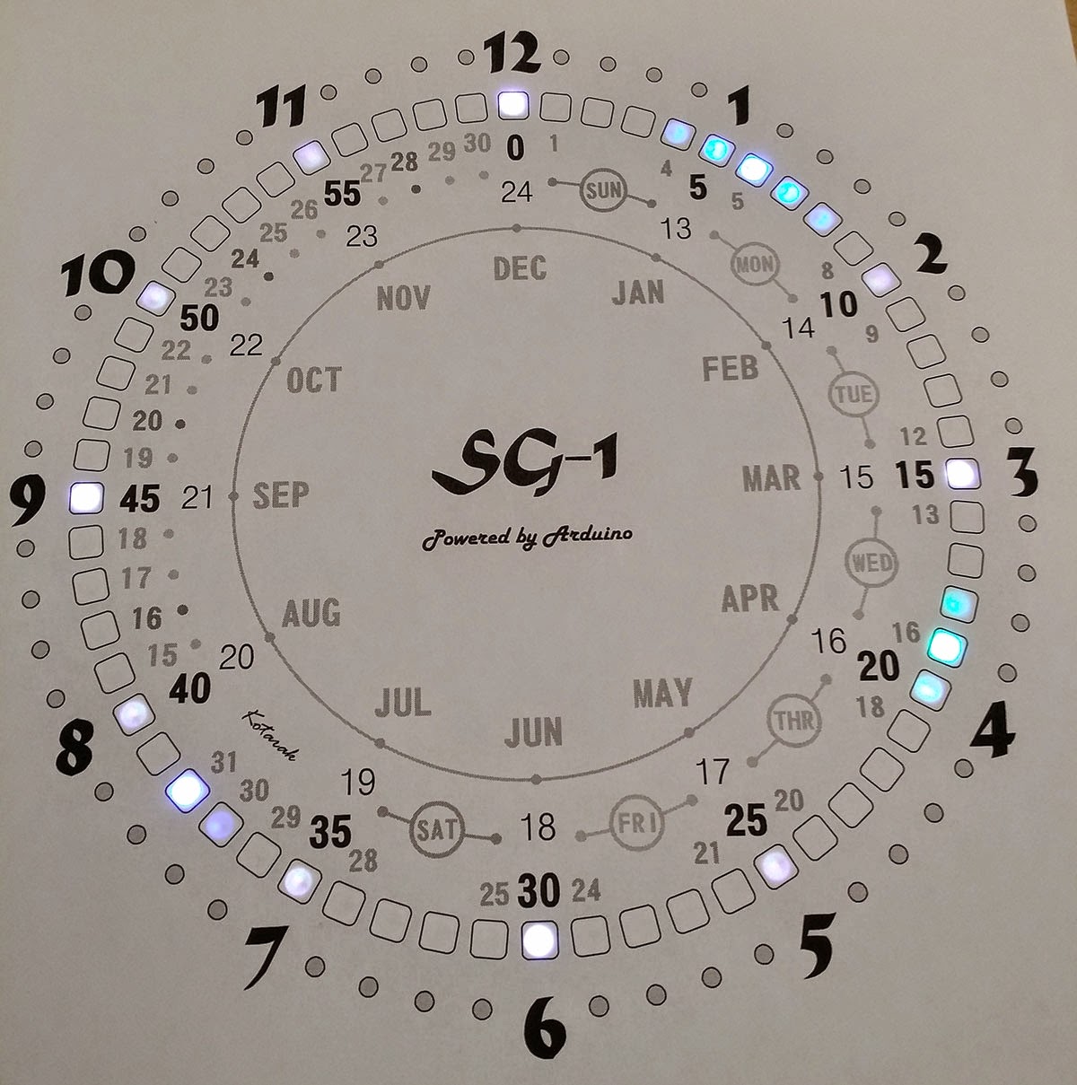
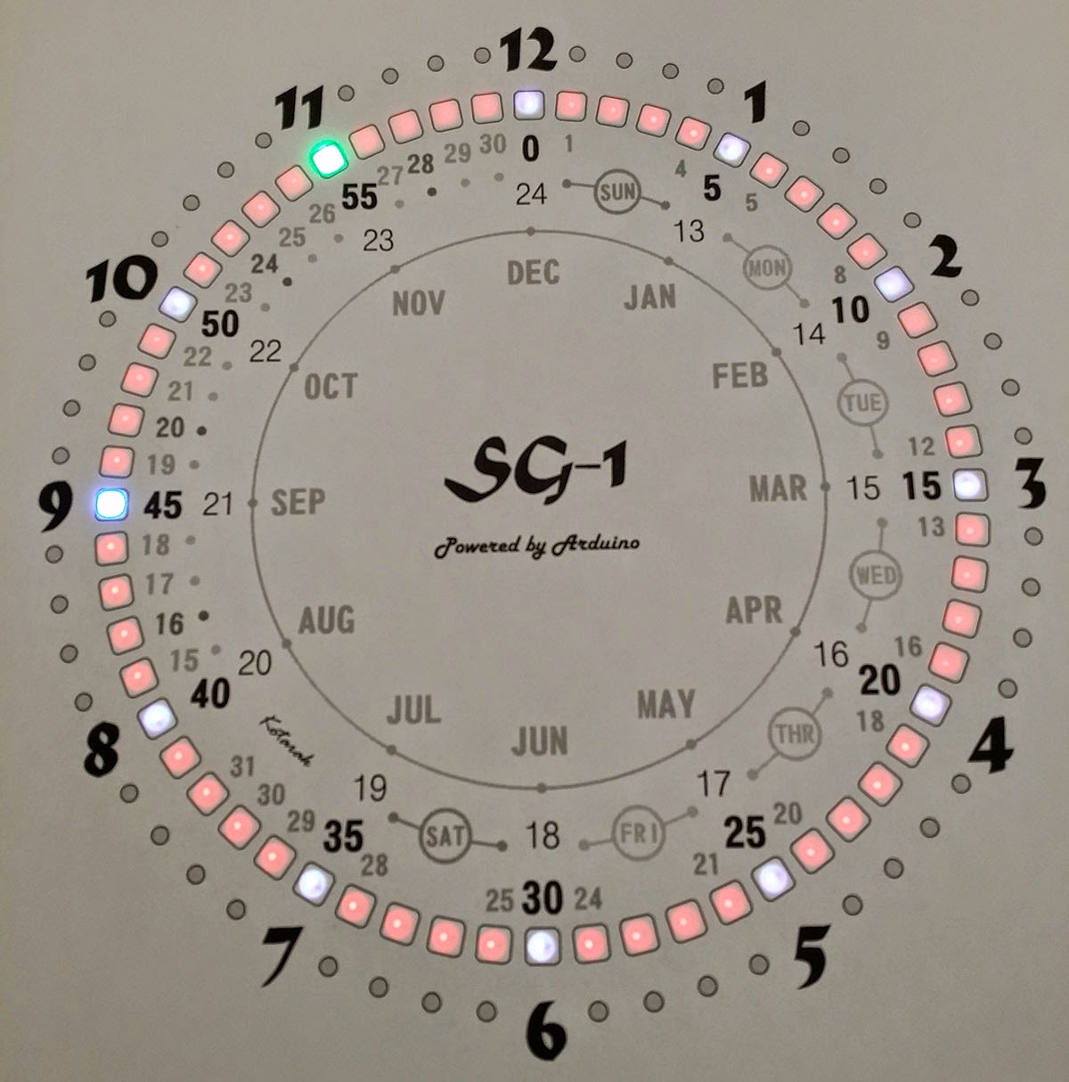
The Main Color Set - Time is 11:14am (22 sec)

Main Color Set - Time is 1:19pm (37 sec). The Hour color changes to indicate PM.

Custom Color Set - The color of  each element of the display can be configured independently with a serial console and a text menu, displayed by the firmware. This Color Set has 2 modes and can be configured as either Dark (display off) or Custom Colors (User-defined). 
All colors and clock parameters, including alarm times, modes, sun Rise trigger level, etc are saved in the EEPROM. ChronoDot has its own backup lithium battery so a complete power failure will not affect the clock.

Simple Mode - Hour, Minute and Second  - Time is 11:14am (33 sec)


 Calendar Mode : Date is May (orange) 1st (blue), 2015 (white) Friday (green). The day of the week color changes to red for the weekends. The inner part of clock's face helps to quickly determine the date. The hour dots are used for the month, and the date and year are displayed only in-between the dots. It is a bit awkward at first because of the 4 day increments per segment, but one can quickly get used to it. Only the next 32 years are displayed in two runs - each is 16 years, then a new clock face is needed to reflect the next 16 year segment.

 Alarm OFF (left) and Alarm (ON). Alarm for Week days only. Alarm time 7:00am.
One of the color sets displays the Alarm time and mode. If a dual mode is selected - for instance Alarm on Weekdays and Weekends. the display will alternate between the two alarm times every 10 sec.

Alarm ON on Weekdays and Weekends. Alarm Time for the Weekends is 9:55pm (a favorite TV show starts :-). Hour, Minutes and Modes are all set with  the 3 buttons.


Sun Rise Alarm Modes - triggered only once a day! It can be triggered between 4am and 9am and the actual trigger is the level of ambient light in the room when the Sun raises. The trigger level is sampled beforehand, using a menu item and it is stored in the EEPROM. 
Some  of the configurable Alarm modes left-to-right: Weekdays Time Alarm + SunRise Alarm on the Weekends, Weekends only SunRise Alarm (no weekdays alarm), Every Day SunRise Alarm

Display Brightness Selector - 59 adjustable levels (left) and Auto mode (right) when the display brightness is controlled by the Ambient Room Light Level. The brighter is in the room, the brighter the clock display will be.

Volume Control (goes to 10 only, not 11:-). Left - Hourly Chime - plays Westminster quarter chimes + Bells for each hour, Right - Hourly Beep mode - beeps on the top of each hour. This selector sets also the volume for the button clicks in menu mode. A special Night Mode (Quiet Hours) can be selected - it disables any chimes during the night time quiet hours (Default is 23:00 to 05:00 but it can be changed and saved by the Text Terminal Menu)

Calendar Set Mode. All functions, modes, times and calendar can be set using 3 buttons and the menu system (using single, double-clicks and long-press actions)
There are a functions which require computer - for example to set the Custom Colors and Mode for the Custom Color Set but everything is saved then in the EEPROM.

Part of the menu system - Yes / No selector for Calendar Setup. 


Yes / No selector for Sampling Ambient Light Level trigger threshold for the SunRise Alarm

 Every hour the clock does a random Star Gate visual effect - I didn't change anything in this part of the code - its all hopo28. The effects and animations are pretty cool!
The alarm song selection is a rather geeky (Star Wars, Indiana Jones Theme, etc), but the clock has a RTTTL Player routine so any Rtttl formated song from the web can be added - the only limit is the available PROGMEM space - currently a little over 256 bytes are left from the 32K.

The Text Menu was enhanced a bit to allow setting of the additional parameters and to provide more detailed status. I also added a separate color element for 3/6/9/12 hour dots.

Now I am working on the enclosure - thinking of something like a picture frame, but will explore other options as well. The clock face needs some improvements as well.
Toying with the idea to use the Light Sensor as sort of  a "Shift register" for the Menu. The user can simply cover with one finger the light sensor and this will change the meaning of the button functions - for instance advancing minutes with one button and when the light sensor is dark (covered), the same button decrements the minutes instead. Another feature I would like to add is an automatic DST but I doubt that ill be able to free up enough program memory for this.

Tuesday, April 28, 2015

Canon EF-S vs. EF Lens shaprness when shooting with APS-C

Since Canon EF-S (S for Small image circle) are the main lenses used with APS-C format cameras, I was wondering what is their quality. There are no L lenses in the EF-S format and I wanted to put them against a similar, kit-grade lens.. I did very simple and un-scientific test and compared 3 lenses - Canon EF-S 18-55mm 3.5-5.6 IS STM, Canon EF-S 55-250mm 4-5.6 IS STM and Canon EF (Full Frame) 28-105 3.5-4.5 USM. These are very inexpensive lenses - both EF-S lenses are often sold as part of the Canon DSLR kits and the Canon EF 28-105mm which was an average (not too shabby but nothing spectacular) lens from the 35mm film days - the one I used was the "better" mark II version (f/1:3.5-4.5, 7 blade, made in Japan). It was a good. well built all-around lens and and a step up from"kit grade" econo zoom lenses at the time (as the EF 35-80mm - a really cheap lens).
All shots were taken with Canon EOS 70D set on manual mode, ISO 500, fully open aperture. The idea was to compare the details in the image thus the lens sharpness. All images are a 100% crop - 1200 x 1000 px  from the original pictures. I chose a subject with a lot of dust particles and imperfections rendering small details.

 EF-S 18-55mm @ 55 mm

 EF 28-105mm @55 mm

EF-S 55-250mm @55mm

Now, this comparison is not quite fair as both EF-S lenes were tested at their very limits where performance is not usually very hot. Still the 28-105mm is the worst of them all even almost in the middle of the zoom range.

Canon EF-S 18-55mm @ ~26mm

Canon EF 28-105mm @28mm
By far - the worst case!

Canon EF 28-105 in "Macro" mode @105mm as close as it will focus.


Canon EF-S 55-250mm did not have such close focus range so I brought the zoom to 166mm to get similar framing, Again it did outperform the EF 28-105mm

So as it turns out - the lenses, bundled nowadays with the Canon DSLR kits are of a much better quality then what you'll get in yester years and will outperform what was considered "an average" lens 15 years ago.