We are continuing with the "Hints and Kinks" category. I recently started working on my N2PK
VNA project. Normally, when I do manual soldering of
SMT devices I rely on "sticky flux" and tweezers to prepare the components for soldering. First, I'll apply flux solution on the pads using flux pen (like the
Kester 186 pen) and then I'll wait a bit, until the solvent evaporates leaving sticky flux residue behind. After applying the flux solution, the right timing is very important for placing the
SMD - too soon, while the pads are still very wet and the board will be slippery making it dificult to position the SMD - waiting for too long to dry and it wont be "sticky" enough for the flux residue to hold the component in place. In the next step, using tweezers I'll place and position the component and then press on it gently with the tweezers (small screwdriver, toothpick or even fingernail might work too). The sticky flux residue helps a lot as the component adheres to the board and doesn't move easily or slides across the PCB when I try to hold it in place by applying pressure. Then I'll just tack one (or a few) of the leads, using very little or no additional solder (only what is already on the pads/leads). When the component is secured in place, I'll release the pressure and continue soldering the other lead(s) first. Then,
Ill come back with solder to the ones I have just "tacked".
The N2PK
VNA project is done entirely with
SMDs and because of the sheer amount of components (over 300), I needed some sort of aid for this soldering procedure.
Here is a very simple gadget for
SMD soldering which I constructed out of parts laying around on my garage workbench. The Bill Of Materials includes 3.5-4" copper pipe (1/2" diameter, plumbing type), 7" small diameter brass tubing stock (~0.13" OD, ~0.1" ID, usually sold in Hobby stores), 6" steel rod which fits nice and tight in the brass tubing (~0.094" diameter, again from the local Hobby store), some sort of weight (slingshot ammo, lead fishing sinkers, etc) and an empty plastic canister from 35mm film cartridge.
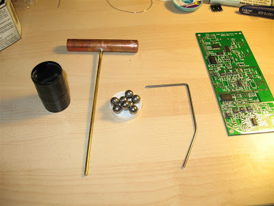 First, I drilled a small hole right in the middle of the 1/2" diameter copper plumbing pipe. I inserted and soldered the brass tubing to the pipe, while making sure that the assembly is a nice straight angle T-shape (because of the large thermal mass of the assembly, I had to use a small propane torch to solder it). The piece of steel rod should be formed into the shape shown on the picture above. Next, I drilled a small hole in the bottom of the film canister and another one in the plastic cap. The holes need to be a tad smaller than the brass tubing's OD so the tubing fits in very tight (with significant friction). I inserted the brass tubing through the plastic canister and the cap, filled the canister with weight (it could be anything small and heavy - nuts, bolts, lead fishing weight, marbles or slingshot ammo (as in my case)). Than, I inserted the end of the steel rod into the brass tubing.
Done!
This simple 15 minutes project will give you a great "third hand" for SMD soldering. The cool thing about it is that it is very easy to control the amount of downward pressure on the components - just slide the film canister up or down on the brass rod for fine control or open it and add / remove weight for coarse. Also, the film canister could serve as a solder dispenser - it can hold a small spool of solder wire which can be pulled through another small hole in the cap. Yet another possibility is to house inside the film canister a couple of 3V lithium batteries, on-off switch can be installed on the plastic cap and connnected to a White LED at the end of stiff insulated wires.This can server as "goose-neck" type of miniature work light, illuminating the immediate area of soldering. Small magnet could be glued to the canister to keep handy small parts and components. Even a small magnifying glass can be attached somewhere - what other features can be added is limited just by your imagination.

The soldering weight is pressing onto chip, ready to be soldered. If the steel rod rotates too easy inside the brass tubing, glue can be used to fix it in a straight vertical position.
 This gadget has a small footprint on the workbench and it can be used with almost any size boards. It can be used inside larger equipment enclosures without the need for removing the circuit boards.
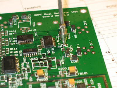 In addition, special tips could be fabricated for the end of the rod and used with different shape and size components. The tip in the picture was made out of an old food thermometer probe - something I just had in one of my junk boxes.
 The very tip was shaped to have a flat face. This picture shows a 0805 SMD resistor ready for soldering. One added benefit is that the metal (nickel-plated copper) tip works as a miniature heatsink for the component being soldered, reducing the chance of overheating and thermal damage.

 The N2PK is a serious SMD soldering exercise - over 300 components on the main PCB and over 700 solder joints. The blank 4.3 PCB was ordered from VE3IVM. All parts are from Digikey. The only additional components were the Valpey Fisher Master Oscillator and the Minicircuits transformers. The VP XO is a very difficult component to find! There is an alternative with Connor-Winfield MO, available from Digikey but I was lucky to find the Valpey Fisher part. I installed all components on one side of the PCB and then moved to the other.
 The N2PK VNA is an advanced project - high part count / desnsity on both sides, some fine pitch ICs (not very easy to solder pin-by-pin) and some components in very small packages. Good soldering skills are a must as well as a good set of tools, soldering materials and soldering iron with fine SMD tips (I used Weller WESD51 with ETP / ETH tips). I worked on the board for about 2 weeks spending a couple of hours almost every evening. I could have done it much faster but I was taking my time, double-checking and making sure that there are no mistakes. Troubleshooting is difficult with SMDs and the capacitors are not marked which can cause a lot of headaches should one makes a mistake with the components. My approach was to install all components (small-to-large size order, but starting with the ICs) of the same type/value together, while working on the top side first. After the top side was completed, I did the same thing on the bottom side leaving all connectors for last. I made sure that there is only one type/value components out on the bench at a time to prevent confusion. How well I've done we will see once it is powered up.


