Thursday, February 26, 2009

M3 Electronix LCR Meter

The LCR Meter by M-Cubed Electronics is another very nice kit - IMHO - a must for every workbench. The kit is using very high quality components and PCBs. Included is a powder-coated aluminum case which gives the LCR Meter very professional look. This LCR Meter by itself has an enormous amount of features (all listed on their web site). There are also a few optional test fixtures available. The accuracy is impressive for a kit - basic accuracy of 0.2% using the supplied calibration resistors. The best part is the use of the "4-wire test method" which eliminates errors caused by the test leads and fixtures - a feature normally seen only in high-end test equipment. Upgrades of the firmware are done by sending the unit back to M-Cubed. There is a JTAG connector on the main PCB which allows for re-programing of the PIC but the firmware code is not made public. All SMD components (incl. the PIC) were pre-installed on the PCB along side with some other components, needed for the initial programing of the PIC (crystal oscilator, a few caps and the JTAG connector). The rest of the components were sorted by type in plastic bags. The assembly instructions are very clear and logical. The only gripe that I have is about the capacitors - some of them are small and on the top of this, some of the value markings were partially erased. Even with the help of my Zeiss-Winkel microscope I was unable to identify some of the caps just by looking at them. I had to use another LC meter to actually measure their values - this is not a problem if you have a LC meter handy but the irony is still there - you need a LC meter to build LC meter. Another small issue is the power connector - a male 5.5mm x 2.1mm barrel connector is not provided with the kit and you have to find one - I rather pay a little extra and get it with the kit instead of wasting time to look for the proper connector. Other than that, the assembly went very smooth over a couple of evenings.

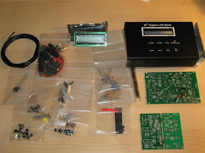
This is the content of the kit right out the box. Calibration resistors are also provided with the kit. The basic kit comes with a probe made out of 4 Pomona-style clips - everything need to construct the probe is supplied with the kit.

These are the 4 boards - Input board, Keyboard board, Main PCB and LCD. Most of the resistors supplied with the kit are of the 1% tolerance type but there are also some 5%. I had plenty of 1% resistors in stock so I replaced pretty much all of the 5% resistors. This might not improve the accuracy a lot but at least the 1% (blue body) are metal-film type resistor with more stable values than 5% carbon-film type. The specified accuracy for the meter is between 0.2% and 0.8% when calibrated with the supplied 0.1% calibration resistors.

The PCBs are "sandwiched" together (using connectors and stand-offs) in the aluminum enclosure. 5-pin DIN connector (on the right) is used to connect the test probe or fixture. On-off switch and the power connector are wired on the left side. Very little space is wasted inside the enclosure and the PCBs are densely populated as well.

This is the finished meter. This meter is using the 4-wire probe method for measuring DUT (Device Under Test). 2 wires are supplying and measuring the AC (0.5Vrms) current thru the DUT and 2 other wires are measuring the voltage across the DUT. This allows for a very accurate measurement canceling out the error introduced by the probe. Furthermore, I increased the accuracy by calibrating the meter with my own 0.01% resistors instead of using the supplied 0.1% calibration kit. If an accurate Ohm-meter is available, the firmware allows for correction of the calibration values and then the supplied resistors can be used just as a "transfer" standard. On this picture high-current 270 uH inductor reads 263.8 uH.

During measurement, the display shows additional information such as the test frequency used for measurement (adjustable up to 15.6 kHz), the Auto-range mode, currently used range, test model (parallel or series), secondary value (ESR in this case) etc. Capacitor with marked value of 5.6 pF and tolerance 5% reads 5.56 pF. There is a menu option for the averaging mode - higher averaging results in more stable measured value. The test frequency is very low - only up to 15.6 kHz (there is an EU version with max freq. of 25 kHz) - not really RF range measurments but gives an idea.

The power supply for the meter should be between 9V-13V. Current draw is about 200 mA . Using the small 9V alkaline battery is out of question - it will last just a few minutes. The backlight can be switch off but the current is still too high for such battery. I am using 2.9Ah 12V SLA battery to power the meter.

This picture shows the inductance and Q for 330uH inductor in "series" model (Ls).


I built a few different sets of probes - Kelvin clips, 4-wire Pomona-style clips and SMD tweezers.
The Kelvin clips probe is the best all-around type. One half of each clip carries the Drive and the other half the Sense signal. It has the best accuracy for testing leaded components. The 4-wire clips probe is useful for testing transformers (there is a special mode for this), already installed components or using it with a small PCB fixture for quickly checking / sorting multiple components (there is a SORT mode alowing a tolerance value to be set and and audio beep indicating if the tested component is conforming or not). The SMD tweezers are a bit less accurate when measuring capacitors due to stray capacitance in the actual tweezers.

Tuesday, February 10, 2009

M3 Electronix Semiconductor Analyzer

A little known company called M-Cubed Electronix is selling an excellent little kit - PIC based Semiconductor Analyzer. It is one of those "I don't know how I managed without it?" things. On their web page - http://www.m3electronix.com/ there is a plenty of information about the features of this Analyzer - it fills a whole page so I am not going to relist them. From hardware point of view there is nothing special - just a PIC, LCD, 3 analog multiplexers and an array of precision resistors. used to set different measurment ranges. What is amazing is the firmware inside the PIC - the Analyzer is using mathematical models of semiconductor devices to detect the DUT (Device Under Test) and measure its parametters accordingly. I must say that this little Analyzer has an impressive accuracy and set of features and it is "a must" for every electronics workbench.

All components are high quality - no surplus stuff. Components are sorted by type. The plastic enclosure (sold separetly) is somewhat bulky anc could be better but it works. Assembly instructions and user manual are in digital form (CD).

Here is the complete PCB and Display Board. On this picture, the PIC is not istalled yet in it's socket. Upgrades to the software are free when available (requires shipping of the old PIC back to the company or buying a new PIC with the upgraded firmware)

The finished analyzer. Device Under Test is an ancient Bulgarian-made Germanium Transistor (GT2 306). There is no specific order to connect the test clips - the analyzer will automatically detect and display the DUT pinout. Every 5 seconds the display changes, scrolling thru a few data screens and showing various test results. After 30 seconds the LCD backlight is switched off to conserve power.

Here is another data screen. Diodes are connected only between the left and right test clips. The feature, detecting internal short (fault condition) in components can be used as ohm-meter for up to 50 ohms.

One small modification I have done is to drill a hole to the right of the LCD and glue a micro-switch connected to the calibration jumper. This allows me to perform calibration without opening the eclosure. I might drill another small hole for access to the trim-pot controlling the display contrast.

Thursday, February 5, 2009

Palstar AT2K

Palstar makes some of the best antenna tuners out there! Last year after much research I got their AT2K model. The build quality is simply amazing. This tuner almost tunes my standard G5RV on 160 meters. It also work on 6 meters due to the smaller roller inductor. The built-in Peak-reading watt/SWR cross-needle meter works really well and with very good accuracy.

Internal picture of AT2k. Most components are manufactured in-house by Palstar, including both variable capacitors and the roller inductor. The quality of the components is impressive - everything is very solid and heavy duty - indeed "built like a tank". All solder joints are perfect.

Roller inductor, 160m inductor (toroid) and switch-in relay. The high-power balun transformer (toroid) is visible at top-right.

Load and tune high-voltage variable capacitors - top-left is the power/SWR detector, top-right is the PCB of the peak-and-hold circuit. At bottom-left is visible the ceramic rotary RF switch.

Palstar AT2K and Heathkit SB-200 in my shack. AT2K looks stylish and it is very easy to operate! The two vernier dials allow for very fine tuning.

2010 Update: The current version of AT2K was changed from the original design. As a cost-saving measure, the internal 4:1 balun (used with balanced antennas) was removed from the tuner and it is now sold separately as an external option. Another change is in the inductor - the original inductor was 18 uH and was padded with extra 10 uH inductor for 160m only. The new inductor is 28 uH, eliminating the extra inductor, relay and switch at the expense of the tuning resolution.

Wednesday, February 4, 2009

"Gettering" GU74b / 4CX800A

There is no such thing as a perfect seal! Vacuum tubes (especially high-power transmitting tubes) not used for a few years might exhibit serious problems if put into service without a prior conditioning of the vacuum. With time, gas molecules leak inside and/or are released by the tube's internal components. With years and years of storage, the vacuum could deteriorate to a dangerous level and once the tube is used for the first time it could "flash-over" - the gas molecules inside will become ionized by the electron flow and this will create a flash of high-temperature plasma between the cathode and anode, damaging the grid(s) and other internal components. A chemical composition, called "getter" is factory deposited inside the tube to complete and maintain the quality of the vacuum (the getter is visible as the shiny, black-metallic area on the inside wall of the glass envelope (in smaller tubes)). In power tubes, the activation of the getter is done by heat. Therefore, it is recommended, before putting into service a power tube with very long on-the-shelf life (more than a couple of years) to condition the vacuum first. This is done by applying power to the filament (cathode heater) only and leaving it on for a period of time. The hot filament will heat up the getter and also will improve the vacuum by itself (gas molecules will react with the hot tungsten filament and the cathode surface, forming chemical bonds and effectively extracting them).

Here is a simple fixture I used to "getter" my newly acquired GU-74b tubes (NOS, manufactured in 1990-92).

The "chimney" is made by cutting the top portion of a plastic soda bottle ("Classic Seltzer Water" sold at Costco to be more specific :). The cooling fan is from computer power supply. The tube MUST (!) be cooled with forced air while being "gettered" or the high temperature will damage the metal-ceramic seals and destroy the tube. The fan is raised about an inch from the surface to allow for air intake. I slowly raised the filament voltage from 3v to 12.5V (12.6 is the nominal voltage) over a period of 5 hours in 5 steps (3v, 5v, 7.5v, 10v, 12.5v) using variable power supply. I, then left the tube running with the nominal filament voltage for about another 8 hours. The fan should run continuously, powered by a separate 12V supply. The current drawn by the heater is around 3.6A (maximum allowable is 3.9A). Absolute maximum voltage for the filament is 13.3V but it should never be reached! Recommended operational voltage for the heater is 12.6v and exceeding this voltage is not healthy for the tube. Measures must be taken to avoid short in the power leads (at the tube's pins) - best is to use proper tube socket but wire-wrapping with solid copper wire (AWG 18 or 16) and heat-shrink tubing insulation could work too.
At the end of the "gettering" procedure (after power is disconnected) is also a good time to conduct a few electrical checks for possible internal short between various tube components - using just a simple ohm-meter, while the tube is still hot (! be careful handling it to avoid burns - use gloves) and one more time when the tube completely cools down. Check for short between the heater and the Cathode, between Cathode and 1st Grid (G1), between G1 and G2 and finally G2 and Anode. While the Cathode is still hot, it is normal to see somewhat lower resistance between the Cathode and the grids or the anode - it is a vacuum tube after all and it will conduct current if electrons are emitted by the hot cathode. This resistance will gradually increase as the tube is cooling down.
After installation in the amplifier it is recommended to start using it at low power and low duty cycle (maybe just starting in SSB mode) and gradually increase the power output.

AC Line Voltmeter

In most tube amplifiers there are at least a couple of supply voltages which are not regulated! Usually, these are the anode (plate) voltage (B+) and tube's heater (filament) voltage.
It is difficult and expensive to regulate a few kilovolts power supply in the case of the anode supply and it is big-n-heavy to regulate 8-10A of filament voltage. Instead, a form of regulation (or rather adjusting the voltages in the "ball park") is done via power transformer taps in the primary winding. Selecting the proper transformer tap is very important for proper operation and tube's health but this means that a stable AC line voltage is as important. Often under heavy load, the AC line "sags". Sometimes the utility company delivers power which is "out of specs" or your neighbour is welding in the garage - all are things that can affect your line voltage and might yield for adjustments in the way the amplifiers is used.
In other words - monitoring the AC line gives useful information during high-power amplifier operation.
I decided to build a digital AC line voltmeter for my shack. (as mentioned above - a useful thing but It also looks cool - I like red glowing numbers in the darkness of my shack, it contributes to the ambiance :-)))
AC power is delivered to residential buildings with 3 conductors from a "single phase" center tap 240V utility transformer (located near by). The center tap is the "neutral" conductor (usually grounded too) and there are two "hot" lines - 240V between both "hot" conductors and 2x120V (each half of the secondary) between each "hot" (end of the secondary) and "neutral" (center tap) conductor. In the electric panel the loads (circuits) should be distributed evenly on each half of the winding but for 240v, power is taken from both ends of the secondary.
If a 240V line is available for the amplifier this will allow also for monitoring each half of the secondary - both 120V lines coming to the house. I decided to implement this ability in my voltmeter. This way I can keep an eye of what exact is coming to the house and determine if my utility transformer or house electric panel is not loaded evenly.
The shopping list included the front panel mountable digital AC voltmeter (500V) UP5135 - $12 from eBay, electrical box from Home Depot, 12V/300 mA transformer, 7805 IC, bridge rectifier and a few switches (all from Radio Shack) as well as some other parts from my junk box (filter caps, etc).
The digital voltmeter unit (UP5135, AC 500V version) I am using doesn't have an isolated input so it is important that the meter's +5V power supply is electrically isolated from the measured voltage. This is done very easy by using a small transformer for the built-in 5v supply and not grounding the "negative" side but leaving it to "float" with whichever voltage is measured. (I let the smoke out from one of these meters by testing it using my *grounded* Alinco power supply. When connected to measure the 240V line, it shorted trough the negative side (ground) of the power supply - it destroyed the main IC and evaporated a few PCB traces in the meter.)


Internal look of the AC voltmeter. The board of the meter unit is on the left, transformer and rectifier on the bottom-right and the voltage regulator and filter is on the top-right.


3 switches are recessed in the enclosure - two on each side are switching the input of the meter to measure the 240V line and both 120V lines (by connecting one of the 2 inputs to the "neutral" line and the other to a "hot" line). The switch in the middle is an ON/OFF switch for the meter.


This is the finished meter in my "amplifier corner" showing the 240v line voltage!