Thursday, May 11, 2023

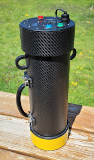
Modifying Scionix-Holland 38B57/1.5M-E1 Scintillating Detector

 Commercial scintillating detectors are usuallu very expensive - hundreds, often thousands of dollars for a good size NaI(Tl) detector. Such detectors are not always affordable for amateurs, even on the secondhand market but for many applications they are the optimal, and sometimes the only solution.

There is a hidden, and often overlooked and underestimated gem though, made by a leading in the scintillator business Dutch company - the Scionix-Holland 38B57. This detector is nearly impossible to beat when it comes to value and it is pretty much "the best bang for the buck", delivering an incredible performance for its very low cost on the used parts market. The detector was manufactured as an OEM part about 10-15 years ago and not available for purchase as "new" but there are plenty of salvaged units out there, offered by various Internet sellers.

The 38B57 is a "classic" NaI(Tl) detector - the crystal is 38mm by 57mm (1.5" x 2.25"), surrounded by reflective powder, coupled with a 38mm Hamamatsu R980 10-stage head-on PMT and mounted in an Aluminum + Stainless Steel tube enclosure.

38B57 is employing an integrated design - the NaI(Tl) crystal is not encapsulated in its own aluminum canister, but it is directly interfaced (glued) to the PMT's Head-On photocathode window and then both, PMT's front part and the scintillating crystal are sealed together in an air-tight aluminum can. The assembly is wrapped with the Mu-metal magnetic / electrostatic shielding and together with the VD PCB is housed in a stainless-steel tube with an aluminum end-cap. 

The integrated design keeps the cost down, but it means that this detector is not really serviceable beyond its voltage divider circuit / PCB - crystal and PMT cannot be decoupled from each-other and replaced without the complete destruction of the detector - this is one of the down sides of such design.

38B57 on the other hand, is a really a high-quality, spectroscopy grade detector and the lack of an additional glass window in front of the crystal improves the resolution by reducing photon refraction and/or reflection which would normally occur with the extra glass window of an encapsulated crystal.

These detectors are part of the Exploranium GR-135 RIID device and hundreds such units are being decommissioned all the time by various US Government agencies (Border Patrol, Cost Guard, etc. ) and sold to equipment recyclers / salvagers.

These detectors will often show up on eBay for as little as $80/ a piece (at the time of this writing, but prices do change) and sometimes for even less, making "good size NaI(Tl) Scintillator for under $100" possible!

The 38B57 detector located in its black, shock-proof rubber protector, inside an Exploranium GR-135 Radioisotope Identifier unit. The white connectors on top are how the detector is connected to the electronics - the left one is the temperature sensor for compensation and the right one is for power to the detector.

Obviously, if the PMT or crystal are damaged because the unit was mistreated or accidentally dropped, the detector goes in the garbage bin but if they were treated well and are in a good, working condition, the detector can provide excellent post-service life as a Gamma Scintillator (Counting or Gamma Spectroscopy probe) - I routinely measure the FWHM resolution to be better than 7% (@662keV) for the 38B57 detectors. This makes it an excellent choice for those who need a scintillator probe, are just beginning and want to try Gamma Spectroscopy and are on a budget. 

I, actually started my Gamma Spectroscopy experiments years ago with such detector.

Unmodified, freshly decommissioned detectors.
I cut off the connectors in order to remove the detector without damaging the protective rubber booth.

As the detectors are removed from the Exloranium GR-135 units and sold on eBay, they are not directly useable - they have a custom voltage divider circuit with transistors and diodes in the last stages, intended for use with the GR-135 hardware and must be modified with a "standard" voltage-divider circuit to get the best performance for both, linearity and resolution.  Even the original connectors and the way they are powered is specific to the GR-135 unit. People have tried to use them without any modification, but the results are not great, and linearity is very poor. 

The simple and easy to do modification brings it to a completely new level and one will be rewarded with a very capable detector once it is done.

The modification process consists of removing the original voltage divider, installing a "classic" VD circuit with appropriate impedance and mounting a coaxial connector on the housing.

This modification is not difficult but requires basic electronics, soldering and mechanical skills and one should be comfortable, working with SMD components in order to perform the procedure.


Modification

Funny enough, the most difficult part of the modification process is opening and removing the rear aluminum cap of the detector.

The cap is glued very well, with 2 different types of adhesives (including a special conductive adhesive) and one must use a heat-gun, an utility knife, flathead screwdriver and some patience to take the cap off. 
Fortunately, there are no heat sensitive components in the very back of the housing, but heating must be done quickly before the heat creeps down the housing, towards the NaI(Tl) crystal. 
TIP: Holding the detector with a moist paper towel can provide additional cooling and heatsinking effect to the crystal housing while performing this procedure.

Enemy #3 of these inorganic scintillating crystals are rapid temperature changes which can cause the crystal to crack. (Enemy #1 is moisture and Enemy #2 is mechanical shock)

It requires quite a bit of heat for the adhesive to fail and let the cap go. 

Inserting the blade of the utility knife between the edge of the tube and the cap while hot, allows for the cap to be pried off - this action must be carried out repeatedly at different spots around the perimeter of the cap until it comes off.

If the cap doesn't budge initially, just reheat quickly to a higher temperature, while monitoring the temperature of the crystal housing and once the cap is open, slowly cool down the top, hot edge, of the stainless-steel tube.

The aluminum cap can retain heat, so the process is as follows - heat up the cap and the edge of the stainles-steel tube, then quickly put down the heat-gun and try to pry it off with the utility knife, then repeat it as many times as needed while changing the position around the perimeter of the cap.

Once the utility knife blade widens the gap enough to slip in a flat-head screwdriver between the edge of the stainless-steel tube and the rim of the cap, things will become easy - twisting the screwdriver applies quite a bit of force to pry the cap open.

Most caps will come off quickly and easily, but some might have an excessive amount of glue and can be "tough cookies" to crack.

Once the aluminum rear cap is removed, this is how the detector looks on the inside. 

Next step is to remove the silicone sealant, cables and the cable grommet.

DO NOT try to remove the stainless-steel tube from the bottom, aluminum part of the housing in order to gain better access to the PCB - it is not needed, and any such attempts could lead to the destruction of the detector!

All of the work on the PCB is carried out through the back opening.

I cut the cables for this picture, but actually the wires should be de-soldered and completely removed. The picture shows the original Voltage Divider, with the transistors in the last stages. It is a tapered VD and the total impedance is fairly low - around 12MOhms.

Most components of the original VD must be removed, and some will be replaced with different values. The only components that stay are the 3 capacitors shown on the picture - everything else, marked with red "X" in this picture, must be de-soldered.

The best and fastest way to remove these SMD resistors is using 2 soldering irons equipped with fine tips (I use ETP tips for this task with my Weller stations). This method also carries less chance for PCB damage. Each resistor is heated simultaneously on both sides and picked up by the two soldering iron tips as if tweezers are used. It takes me just a few minutes to remove all of the unnecessary components. Solder wick is used to clean the pads and prepare them for the new resistors. The old soldering flux can be cleaned off with alcohol pads or alcohol-soaked Q-tips.

This picture shows how the PCB should look like after de-soldering the original voltage divider. 3 out of the 4 SMD capacitors (10nF/200V) are left in place. The 4th capacitor on the very left is removed and later a resistor will be installed in this position.

PMT Check (optional)

After removing all of the necessary components, it is a good time to conduct a check of the PMT integrity. 
The PMT is sealed and glued inside the stainless-steel tube and it is difficult to tell if the detector has been dropped and the glass envelope of the PMT is broken.

Fortunately, one can do a quick electrical check - all that is needed is an ohm-meter with high resistance range (preferably 100M) and a flashlight. The positive (red) lead of the ohm-meter is connected to the first dynode (Dy1) and the negative (black) lead to K (Cathode).
On the PCB these two test pads are where originally the red wire was connected (K) and the white wire (Dy1).

Normally, in dim light, there will be very high resistance and the ohm-meter will show "open circuit".

Shining briefly with a flashlight in the back of the PMT, thru the PCB's center hole, where the glass evacuation port is located should show a lower resistance on the ohm-meter - around 50M or less (depending on the flashlight power). 
This is an indication that the PMT is good and under vacuum.
The light knock out electrons from the Photocathode and they cross thru the vacuum to Dy1 acting as Anode.
If the resistance remains high (infinite), there is a possibility that the PMT is broken. 

Next step is to install the SMD resistors for the new, "classic" voltage divider. 
I have discussed choosing resistors for PMT VD in other posts but for general purpose (counting with Eberline or Ludlum meters or other battery-operated meters for example) 10 MOhm resistors are normally used. The Hamamatsu R980 PMT used in the detector is a 10-stage PMT with 2R (20M) between K and Dy1 and R(10M) for all other resistor positions (between the rest of the Dynodes).
 The footprint on the PCB requires 1206 package resistors.
The total impendence of the VD will be 120M, which results in minimal voltage drop even with very low current HV power supplies. 
(For Spectroscopy applications, a lower value for R/2R should be used - 1M or 2M is generally a good choice.)

I used 10 Mohm / 1/4W / 1206/ 0.1% tolerance resistors - Digikey part # 749-MCA1206MD1005BP500CT-ND - Vishay High Stability chip resistors.

Resistance tolerance is not super-critical as there are small factory differences in the PMT's Dynode stages to begin with. Thick film resistors with 1% tolerance, should work just as well and they will be more economical. 

All resistors should be installed as shown on the picture.

(tip: buying these resistors in quantity of 100 or 500 pcs from Digikey is more cost-effective, especially if more than one detector is modified - each detector needs 12 resistors)

Key points on the picture above:

A. Resistor is installed on the pads of the previously removed capacitor.

B. Resistor is installed on top of the capacitor and in parallel, soldering the resistor terminals to the capacitor's terminals.

C. Two resistors in series are installed between Dy1 and K. Single 2xR resistor (in this case 20M) can also be used but I found to be more convenient if I use 2 resistors as the distance between the pads allows for this, looks clean and helps if 2R is not one of the standard values.

This is how the PCB should look like after all of the resistors are installed. The yellow wire is connected to the PMT's Anode (P) pad and supplies both, HV Bias to the PMT and return signal - it returns back the positive pulses generated by the PMT to the external circuit.

The grounding lead wire, attached to the detector's housing (circled in red) must be connected to the K pad (PMT's Cathode). The stainless-steel part of the housing acts as electrostatic shield for the PMT and must have solid ground connection.

After the K lead (black wire) is installed, the grounding wire to the housing is connected at the junction of K-2R. 
If the original wire is not long enough to reach the K pad, it can be extended with a piece of bus wire, as shown.

The two pads circled on the picture must be bridged with a short piece of jump wire. 
This is an important step and should not be omitted!
If this jumper is not installed the detector will not work. 

Here are the schematics of how the modified detector should be wired. 

The aluminum cap is drilled in the center and a female BNC connector is installed - I recommend using a good quality connector with Teflon center conductor, like Amphenol UG-625/U. 
Alternatively, a MHV or even SHV connector can be used but there is not much clearance on the inside and fitting a standard SHV bulkhead connector will be rather difficult and will require modification to the back side of the connector.

Standard UG-625/U BNC connectors will also require some trimming of the center terminal to prevent it from touching the PCB or the PMT's evacuation tube in the center. Half of the solder cup can be removed with wire cutters, leaving enough for a reliable solder joint.

The drill diameter for the hole in the cap is 3/8" for a round connector and if the connector barrel is D-shaped (to prevent rotation), then 11/32" drill bit is used, and the rest is shaped with a set of small round and small flat files, until the connector can just fit through the hole without being able to rotate. Using connectors with D-shaped barrels is the better choice - it locks the barrel in place and prevents the connector from loosening itself when operated.

The yellow and black wires (silver-plated stranded wire with Teflon insulation) are soldered to the BNC connector. These wires are about 1" long (actually, they can be a bit shorter than this) and are carefully bent in a spiral fashion and routed in a way not to touch the board or components when the cap is closed.

The original cable opening is sealed with a piece of self-adhesive copper tape and a length of Kapton tape on top. The housing must be completely light-proof (!) and air-tight. Black RTV sealant around the BNC connector (on the inside) can be applied before the connector's lock-washer is placed and nut is tightened.
I highly recommend that the BNC connector's lock washer is used to prevent it from loosening.
The aluminum rear cap is glued back with hot-melt glue to the stainless-steel housing - I apply small amount around the perimeter, near the top edge of the cap with a glue-gun, heat up the cap and press it flush.

I also seal the seam between the aluminum part of the housing and the stainless-steel tube with a strip of Kapton tape - just for "good measure".

The modified 38B57 detectors - completed and tested, ready to be installed in Gamma Dogs. After the modification, these detectors can be directly connected to counters such as Eberline ASP-1 or most Ludlum counters. They will certainly outperform Ludlum 44-2 probe for example. 

Here is a Gamma Spectroscopy plot done with one of the modified detectors.
The FWHM resolution for 662keV (1uCi of Cs-137 source disk) is 6.9%. The detector was running on 575V and connected to a Gamma Spectacular GS-USB-PRO. (The second peak from the left is XRF coming off the lead castle - the peak is suppressed due to the graded shielding).
These detectors output ~110 CPS (6600 CPM) for the Natural radiation background at my location when unshielded (~0.1 uSv/h).


"Gamma Spectroscopy Only" Use / 12MOhm Total Impedance VD

If the detector is to be used for Gamma Spectroscopy only, with GS-USB-Pro or a Lab Grade PS driver providing "stiff" HV Bias, lower impedance VD will result in better stability, better SNR and even faster response. 
The 12MOhm VD on the other hand pulls more current and it is too low for portable, battery operated, meters - it will cause a significant voltage drop and an increased battery usage.

The original VD can be modified by removing the active components and only some of the resistors while keeping all of the existing 1MOhm resistors - this is really simple and logical, but I decided to provide the pictures anyways in case somebody wants to follow this guide as a step-by-step.


Only the marked with "X" components should be removed, keeping all existing 1Mohm resistors in place.


This is how the PCB should look like after de-soldering the unnecessary components.

Additional 5x 1MOhm resistors are needed (I used the ones salvaged from other units) to complete the 12MOhm Voltage Divider.

The rest of the modification is just as outlined above.

Tuesday, April 4, 2023

Building a Scintillator, using CsI(Na) crystal and Hamamatsu R6231 PMT

 This scintillator build is not much different than the others except for using a CsI(Na) crystal and 2" / 51mm PMT.

 I understand that people use these posts as a guide when building their own scintillators so I decided to document it as it might provide additional information, which I might have missed in previous posts.

Using Gamma Spectacular PCB for R6231. This PCB is designed for both, single wire (HV Bias + Signal) and 2 wire (HV Bias and a separate Signal line) interface. I populated the PCB for the Single wire interface using R value of 5.6M for the voltage divider. Had to improvise a bit with the 2R resistors between K-G and G-D1 as there was only one footprint per resistor but there are no 11.2M resistors.
Total resistance of the VD is 67.2M.

Voltage-Divider impedance is not a super-critical parameter, but it is important to consider based on the application. For example, with many battery-powered counters and meters where the HV Bias supply can't take much load, high-impedance is preferred as the lower current will reduce the voltage drop. Some low-current PS will drop the output voltage significantly with impedance as low as 60M. In these cases, a total impedance of 120M will work well. High-impedance divider on the other hand will have poor SNR (Signal-to-Noise Ratio) and linearity could suffer as well - for Gamma Spectroscopy with benchtop / lab-grade power supplies, VD impedance of 12M or even lower should work quite well.
For this detector I went "in the middle of the road" with VD around 70M.

Machined PMT rear cap, completed PCB and the PMT ready for the final assembly.

The PMT is a 2" Hamamatsu R6231 - the little brother of R6233. The only difference between the two is really the size - all other specs are the same.
R6233 is one of the best all-around PMTs - I've built more than a dozen detectors with it and absolutely love it - the R6231 should be just as good!

VD PCB installed on the back of the PMT with the two silver-plated, Teflon insulated lead wires. 

Installing the MIL-grade BNC connector (Amphenol UG-625 B/U). 
There is a wire fed thru a small hole in the cap for grounding the electrostatic shield. Heat shrink tubing is added for extra insulation of the Anode lead and both wires are coiled into "springs" and away from each-other before closing the PMT cap so they don't press on the board and stay away from the components.

The photocathode window was thoroughly cleaned with Acetone and any dust particles were removed using micro-fiber cloth and sticky tape until the glass is absolutely spotless. 


The crystal is a "Soviet Era" 40mm x 40mm CsI(Na). Datecode is June, 1991.

CsI is a higher density (4.51g/cm3) scintillation material which makes it more efficient at detecting gamma (better stopping power due to Cesium's higher Z). 
Its light output is 85% when referenced to NaI(Tl) but one big advantage of CsI(Na) when compared to CsI(Tl) is that the emission peak matches perfectly the response of Bialkali PMT photocathode at 420nm wavelength. 
CsI(Tl) on the other hand is better suited for use with SiPM as its peak is at 550nm and cutoff at 320nm.
CsI(Na) is also much faster scintillator with decay time of 630ns compared to CsI(Tl) at 3.5us which allows for higher rate detection. Not as fast as the NaI(Tl) with 250ns decay.

Comparison of the emission peak wavelength and temperature response of both types CsI materials. 
The light yield is slightly lower with 41 photons/keV Gamma for CsI(Na) compared to 54 photons per keV Gamma for CsI(Tl) but greater than NaI(Tl) with 38 photons/keV Gamma.

My crystal is absolutely pristine - no significant blemishes, no yellowing, no cloudiness. It is crystal-clear (no pun intended).
 The glass of the optical interface window was cleaned in the same manner as the PMT's photocathode.

Due to the small difference in diameters between the crystal canister (45mm) and the PMT (51mm), I added a short sleeve from EVA foam around the window area, which will center the crystal during assembly, preventing it from sliding off-center to the PMT. The size difference is very small (~5mm) and there was no need to 3D print a centering collar.

A drop of high-viscosity (100K cSt) silicone fluid is added as optical interface between the two glass surfaces to minimize reflections and refractions by eliminating the air gap between the two glass windows. The silicone oil's refractive index is around 1.41 which is close to the 1.46 refractive index of the borosilicate glass of the PMT.

PMT and crystal are put together and the silicone fluid interface is distributed evenly between the two glass surfaces with repeated, overlapping, wide, circular motion until it becomes a very thin and even layer. The extremely high viscosity of this layer and surface tension prevents it from "running" and it will stay permanently in place.

Strips of vertical electrical tape are used to pull together both, PMT and Crystal with some tension. The tape is stretched during application, and it exerts constant pressure between the two parts ensuring a firm contact. With this small diameter PMT 4 long strips (which loop under the crystal) are sufficient.
Both, crystal and PMT are then wrapped multiple times, around, with special focus on the interface zone so it becomes one tight package.

After completely wrapping the assembly with multiple layers of electrical tape, I added a sleeve of EVA (Ethylene-Vinyl Acetate) foam to serve as mechanical shock protection and thermal insulation for the assembly. EVA foam is a very dense closed-cell foam and does great job for both applications.
The front face of the crystal is also protected by a disk of EVA foam, glued to the crystal's foam sleeve. 
Needless to say, the assembly is 100% light-proof.

The magnetic / electrostatic shield is added as a two-turns sleeve of special Mu-Metal sheet, spot-soldered closed, and the grounding wire is then soldered to the sleeve. The sleeve overlaps the photocathode area and into the crystal canister by about 5-7 mm.

Second EVA foam layer for even more shock protection of the glass-envelope PMT goes on top of the magnetic shield.

After completing the entire assembly, the final protective layer of heat-shrink tubing is applied. 

This is probably the most critical and dangerous part of the assembly process as overheating the crystal can easily cause it to crack. Crystal temperature should not be increased too rapidly. Heat was applied in short burst (with cooling time between them), which allowed the heat-shrink to heat up rapidly but not to transfer a lot of heat at once to the crystal.

Heat-shrinking is not "a must" but provides a nice finish, serves as an additional protective, abrasion / scratch resistant layer and keeps both components - crystal and PMT firmly together.

Just as expected, the resolution is not bad at all and spectrum looks pretty good! 

Running the detector on 600V PMT Bias. For Cs-137 at 662keV resolution is 6.2% FWHM. 

Theremino's algorithm for automatic estimation of the FWHM resolution seems to be a bit on the conservative side so a more realistic value would be actually around 6.0% - not too shabby for a 30-year-old, Soviet Era crystal I must say.

Tuesday, March 7, 2023

Complete DIY XRF Setup

My DIY XRF setup is finally complete - it is comprised of an Amptek X-123 detector using the proprietary Amptek 25 mm2 / 500 μm Si-PIN X-Ray detector element (model FSJ32MD-G3SP), Amptek Pre-Amplifier and DP5 DPP /MCA.

Details about the detector are in THIS post.

On the exciter side, in the past, I have used X-Rays from an Am-241 source (59.54keV). Unfortunately, there is no exempt quantity or a way to obtain high activity, pure Am-241. The ones used in modern household smoke detectors are only 0.9 uCi (unless obtained from the old Pyrotronics industrial smoke detectors with up to 80uCi) but still have the Am-241 mixed and pressed into Gold and Silver foil which has parasitic emissions of the said metals in addition to the Am-241 decay product - usually a fairly strong Np La line emission (from Np-237 decay product). The Neptunium La-line is observed even with recently created Am-241) La at 13.95keV.

I decided to switch over to an X-Xay Tube where the emission can be controlled precisely, the spectrum is uniform with the exception of the XRF emissions from the target material (Tungsten in my case) but this is normally a single element and easy to remove from the spectra.

 I am using Moxtek Magnum series transmission X-Ray tube with Tungsten target - 10W total electrical power (-50kV / 200 uA) controlled by an X-ray source controller of my own design my own design.

The X-Ray tube is placed inside a Lead shield. The aluminum box on the right-top in this picture is the detector enclosure, housing the detector element, preamp, power supply and the Amptek DP5 Digital Pulse Processor.

This is my test setup while doing XRF on a piece of copper foil for initial Energy Calibration.

The aluminum box in the center of the picture is the X-Ray tube's high-voltage power supply module. It is a high-frequency switching supply with a very easy to work interface - 3 output channels (2 analog and 1 digital) and 3 input channels (2 analog and 1 digital) + 12V main power. The supply is very efficient and the current draw is around 1.5A at maximum power.

The X-Ray source aperture and detector at almost 90 degrees so the X-Rays are skimming the surface of the specimen.

This is the first XRF of Copper foil with the new source - the Ka line is at 8.05keV and to the right the Kb-line is at 8.90keV. 
I still need to adjust the detector Peaking Time and Flat Top Time as well as the Slow and Fast detector thresholds - currently I have over 99% of Dead time due to the current settings intended for low X-Ray flux source and too much of primary beam getting into the detector. Revising the geometry of the setup - the placement of the detector, exciter and sample should resolve this issue.

My X-Ray Source Controller works flawlessly, and I am really happy with the end-result.

Saturday, February 25, 2023

X-Ray Source Controller for MOXTEK and AMPTEK Mini X-Ray tubes (Part 2)

A follow up on this post this post

 I needed controller for the Magnum series 50kV / 10W MOXTEK X-Ray source and as it turns out the FTC-200 controller, once sold by MOXTEK is no longer available - it was discontinued due components availability and the Moxtek sales engineer told me - "We expect customers to develop their own solutions." 

This was not a big deal - their FTC-200 controller has very basic functionality anyways, and it is lacking some features that I really needed, so I went ahead and developed my own design to control the MOXTEK X-Ray tube.

Currently, MOXTEK tubes are available in one of 3 configuration - built-in USB controller, I2C interface and Analog Interface. The MAGNUM tube I am using is equipped with the analog interface, but it should be quite easy to add the I2C control capabilities to the controller design as well.

One of my design goals is to have a stand-alone unit with no PC required. I don't want to fumble with numerous PC applications while doing XRF and prefer to have a piece of hardware with actual buttons and dials to adjust the X-ray tube parameters and to operate it. For the fairly simple functionality the controller affords, there is no real benefit from running it with a PC.

I was pleasantly surprised to find out that the AMPTEK Mini-X2 tube uses the same electrical interface as the MOXTEK Magnum series of X-Ray tubes so my controller will work for AMPTEK Mini-X2 just as well which makes it even more versatile.

Update: As it turns out Newton Scientific X-Ray tubes are also equipped with the same analog interface or at least have a connector option for it. (thanks Matteo!) 

Simplified block-diagram of XTC-2000

My source controller is based on the nRF52840 System-on-a-Chip (SoC) using Cortex M4F processor and employs 6 control channels as required by the x-ray source interface - 4 Analog and 2 digital channels. Of these 6 channels, there are 2 Analog outputs (driven by precision 12-bit DACs), used for setting up tube's High Voltage and Emission Current parameters and 1 digital output (5V TTL signal) to turn the source ON / OFF. There are also 2 Analog inputs (sampled with a multiplexed 12-bit ADC) to monitor the x-ray tube's working parameters as they are returned by the Moxtek HV module and a digital input (5V TTL signal) to report when the beam is ON and stable (The filament is fully heated and ready). 

I had to employ Logic Level shifters as the nRF52840 is a 3.3V chip and the MOXTEK module has standard 5V TTL levels for the digital signals. Furthermore, the voltage ranges on the Analog output channels range 0-to-4VDC and I have to use the 4.096V internal DAC reference voltage which means the DAC must be powered with a 5V rail. In reality, the reference is 2.048V and the output op-amp buffer of the DAC is switched to 2X GAIN mode, but still 5VDC DAC power is required. 

(I am playing with the idea to dynamically switch DAC's output buffer op-amp GAIN based on the needed DAC output, using 1X GAIN when output less than 2.024V is required (up to 25kV and 100uA) and automatically switching to 2X GAIN for higher DAC output. This should make the output even more precise.)

For the Analog inputs, I used precision voltage dividers to bring down the Monitor / Return channel voltages in the range of 0-to-3VDC and then used the built-in ADC reference of 0.6V with gain of 5x.

There is also a 5th Analog Input channel, internal to the controller, with its own voltage divider, used to monitor the Low-Voltage Main Input Power and to inhibit controller operation if the controller's and / or tube's input voltage is not within the nominal range. 

OSH Park service delivered again beautiful, high-quality PCBs. The ordering process is very simple and a pure joy - I almost feel sorry I don't have more PCB projects to order. 
The PCB design was done with Autodesk Eagle but I am not big fan of what Autodesk is doing with Eagle (it used to be my favorite PCB app) and very likely to switch over to KiCad in the near future.

The assembled and ready X-Ray Source controller - XTC-2000 (a.k.a. "X-Ray Tube Commander 2000" :-) 
(Chat GPT suggestion :-)

Using a rotary encoder with a pushbutton makes the UI really quick and intuitive. The button (knob-press) is used to enter adjustment mode, and the user can dial first the whole number and then the tenths after the decimal point for each parameter separately.
After entering Set mode, the encoder's push-button scrolls through different digit positions, indicated by a blinking cursor and spinning the knob changes the value. 
The rotary encoder is equipped with its own microcontroller (Atmel SAM D09) which takes care of all of the quadrature input stuff - counts, phase-detection, timing, etc. and just reports the actual tick count, delta, etc. over I2C bus to the MCU. This makes the Encoder really fast and easy to use and I can reset the tick counter with a command if needed. The encoder breakout can also generate interrupt on button press or encoder rotation.

The complete and working controller during bench-testing and DAC/ADC non-linearity compensation and alignment. 
Testing was done by looping the DAC outputs to the ADC inputs and monitoring the loop with a calibrated 6 1/2 digits benchtop DMM. The linearity corrections made sure that both, output and input agree with the voltmeter thru the entire range.
The white (unpopulated in this picture) 4-pin JST connector near the encoder is AUX I2C expansion connector, used for the X-ray tube's temperature sensor or controlling a tube with I2C interface.

Currently, the code is complete and mature, the core functionality is all done and bug-free thus "Version 1.0" release
In the unlikely event of some commercial interest, I might write a more elaborate menu system for setting up various tube types, internal parameters and calibration values, but even at this stage, XTC-2000 has a lot more features, better functionality and better ergonomics than both, the discontinued Moxtek FTC-200 controller and the entirely software-controlled Amptek solution. It also has more safety features and should take better care of the tube's health and operating conditions.

As for the user-interface, in a nutshell - there are 3 modes of operation - MOMENTARY (X-Ray is emitted only while the OPERATE button is pressed), TOGGLE (X-Ray beam is latched, on/off with each press of the OPERATE button) and COUNTDOWN (the user can dial duration in seconds for the beam and start the Timer)

There are many safety features implemented - hardware lockout, software lockout, preventing accidental exposure, emergency beam shutdown, control voltages power-down, tube shut-off watchdog and so on.

In addition, there is a number of features looking after the tube's health as minimum emission time, cooling timeout, temperature alerts, isopower curve ensuring maximum power is never exceeded, mains voltage drop and many more.


When the working parameters are dialed in, the calculated power is immediately displayed on-screen. If the calculated output power exceeds tube's maximum permissible output power for the particular type of tube, the controller will scale the Emission Current to the edge of the permissible power curve and will indicate the change in the calculated power display. This will prevent the tube from being operated at excessive power levels.
While the X-Ray tube is powered on, the controller will also display the actual power level calculated from the Tube's return channels.

As part of the safety and tube's health features, I added external temperature sensing and monitoring using MCP9809 chip.

While designing the PCB, I added an extra I2C bus connector for future expansion such as temperature sensing and control of an I2C tube.

The temperature sensor I am using is MCP9808 - a very accurate and precise chip with I2C interface. Resolution is actually much better than 0.25°C but for my purpose 1° Celsius is completely sufficient and allows faster sample time.

The controller constantly monitors the temperature of the tube, and it will shut it off if temperature exceeds +60°C. The tube will not be re-enabled until it cools down to below +55°C.  With 10W of total electrical power and a massive brass housing this is unlikely to occur, but it offers another level of safety.
The temperature sensor presence is auto-detected on startup - if the I2C cable is not plugged in, the controller will work normally, just without any temperature related features.

The critical part of attaching the sensor is the connection cable between the controller and the MCP9808 breakout board - the cable must be fully shielded due to the proximity to the tube's HV cables and must be of very low capacitance as the I2C bus does not tolerate high capacitance on the signal lines or the useable bus speed will begin to drop.  At 70cm cable length the sensor works perfectly well. The cable I used was foil-shielded 4-conductor USB cable.

The last thing, currently pending on my development list is a suitable enclosure.

Update: As part of the tube's diagnostics, I added a check for deviation from the requested parameters - if the controller detects a difference between what is requested from the tube and what is returned, it will generate "Tube Error" message with a 3-digit error code - each digit represents one of the 3 critical parameters (Filament ready, High Voltage and Emission Current) and the value represents the type of deviation. This makes it really easy and quickly to understand what is going on with the x-ray tube. The check begins 2 seconds after the tube is turned on, allowing time for all parameters to stabilize. There is an option for the user to turn off temporarily this check if needed.